Importing components from library
The virtual environment contains many pre-built components including Monodraught’s Windcatcher range. These components are readily available to be used within any given project, the user is simply required to select and import into their project.
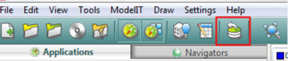
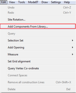
Accessing the ‘Add Components from Library’ dialog
There are several routes available to the user to import pre-built performance components.
Main VE toolbar and menu
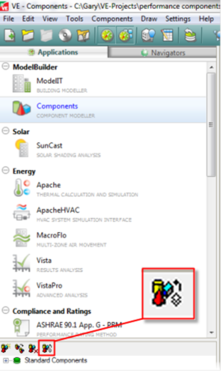
Component Modeller
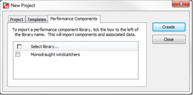
Creation of a new project (File menu: New)
Note: this option differs from those above as this does not give the user the option of being selective (unlike the options above). Instead, this option imports the entire selected library.
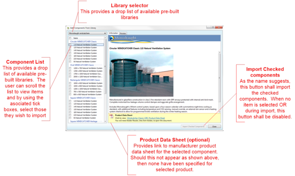
Add components from library
The “Add components from library” dialog enables the user to import pre-built components from one or more libraries.
The preview tab provides an option to view the component in 3D wire frame mode.
Note: importing a performance component from will also import associated data such as constructions, schedules/profiles, templates, systems etc.
Placing components in the model
Once the user has added components to their library, either by importing (as shown above), or by manually creating them, these can then be added to the building model.
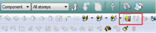
There are two buttons on the main toolbar used for component operations, both highlighted below.
Left to right…
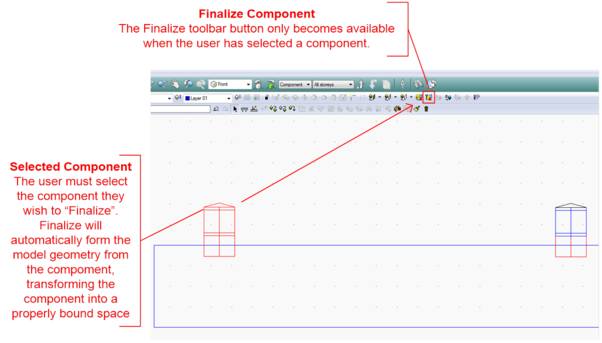
· Place Component – available when the user has selected component to place (detailed below).
· Finalize Component – available when the user has selected a placed component. This option forms properly bound spaces form the component and should only be used for “Space Components”. In other words, for a component that is to become part of the building model geometry. An example of this would be Monodraught Windcatchers.
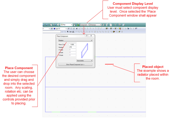
Placing Object Components
Object components are the traditional VE method for component placement. The user should firstly move into body level of decomposition and then select the component display level.
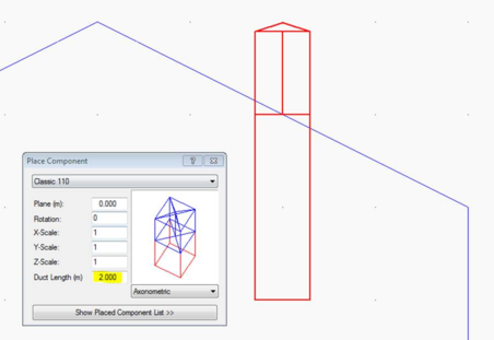
Placing Space Component: Windcatcher
The initial placement of Windcatchers is very similar to that detailed above but do have some crucial differences.
The Windcatcher is essentially formed into two parts.
· The Windcatcher itself
· The Duct(s).
The Windcatcher part should be placed outside the room, whilst it is the duct we wish to penetrate the space and thus, placed within.
Windcatcher components may have variable length ducts; the ‘Duct Length’ field highlighted above allows the user to vary ducts lengths at time of placement.
Note: the small component Viewport is now drawn with a white background and the default view is Axonometric - the "Duct" is drawn in red.
If the VE detects that Windcatcher is not placed correctly, then the user shall be presented with a suitable warning. Typical causes may be that the Windcatcher part is placed within the room (should be fully outside), or the component is not fully over the room. In this scenario, adjusting the ‘Plane’ accordingly would solve this. However, perhaps the easiest solution would be to use the move options from the main toolbar.
Tip: Before choosing “Finalize component” (detailed below) ensure that the component is placed correctly. Once finalized, this component automatically becomes part of the model geometry.
Finalizing Space Component: Windcatcher
When the user chooses to finalize the component, the process takes the component and automatically generates the model geometry, cutting the duct through the penetrating space etc. Before performing this action, the user should take care to ensure that they have placed the component in the correct position before continuing.
Once Finalized, the component is transformed into a group of bounded building model rooms. The rooms that are formed via the ‘Finalize’ stage contain all thermal data as provided by the manufacturer. Macroflo openings, control strategy, constructions etc. are all now exposed part of this process.
Finalize Space Component: Dynamic Room Group Creation
Following the step above, room grouping schemes and associated room groups will automatically be generated as follows:
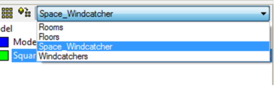
1) A room grouping scheme containing ALL components of given category and type. For example Windcatchers are defined as having a category “Space” and type “Windcatcher”. In this case the scheme would be name “Space_Windcatcher”. This scheme would then contain a separate room group for each different type.
Note: Should the user place and finalize n copies of a particular component, then all rooms of these copies shall be placed within this single room group. This is repeated for each subsequent type.
2) A room grouping scheme containing individual room groups for each component type. For example, type = Windcatcher (as shown above) we therefore, have a room grouping scheme named “Windcatchers”, however unlike item 1 above, this contains room groups for each individual finalized component.
The dynamic grouping detailed above provides mechanism for the user to more easily manage their building models and identify rooms within individual or groups of finalized components.