Generic Heat Source
The Generic heat source (GHS) is a simple and yet flexible model that can provide heat to any components that present a heating load, with the one exception of advanced heating coils, which can be served only by hot water loops. As such, the Generic heat source might be used for modeling a simplified HW loop and boiler in the early stages of a project or for modeling other types of heat sources as needed.
Components that can be served by generic heat source range from radiators, baseboard heaters, and heating coils to steam humidifiers and absorption chillers (via the part load curve chiller dialog). Generic heat sources can be used to model air-source heat pumps, gas-fired furnaces for packaged air handling units, a simplified version of a hot water loop and boiler, various configurations of these with and without heat recovery or coupling to combined heat & power, or just about anything that consumes energy and provides heat and can be represent sufficiently by the data-grid-based part-load heating plant model.
Generic heat sources can be designated to serve domestic hot water (DHW) loads from Apache Systems (DHW loads, tanks, associated losses, and DHW-specific solar HW systems are modeled in Apache Systems; resulting/remaining loads are then passed to ApacheHVAC). To designate a GHS to serve DHW loads, tick the Is DHW served by ApacheHVAC boiler? box in the Hot water tab in the Apache Systems dialog, then, in ApacheHVAC, check the Use this heat source for DHW checkbox in the GHS dialog.
Generic heat sources can operate as or in conjunction with an air-source heat pump as follows:
1) Air-source heat pump (ASHP) as either the primary heat source with the Heating equipment used to model electric backup or as pre-heating for some other device modeled within the Heating equipment part of the dialog. This is done by ticking the Air-source heat pump checkbox in the GHS dialog and specifying the associated parameters on the corresponding tab.
2) Air-to-air heat pump as a backup for an (AAHP) by setting up the ASHP in the GHS dialog as above and then selecting this GHS heat source in the AAHP dialog.
Generic heat sources can also be used to meet remaining load after the heat available from a combined-heat & power (CHP) system or condenser heat recovery (CHR, from the part load curve chiller or from the condenser water loop) has been consumed.
The heating load collectively presented by the radiators, heating coils, etc. assigned to a particular generic heat source is summed at each time step to set the required instantaneous output from the heat source. An allowance is made for any pipe-work distribution losses (these loses do not accrue to the building interior, and thus this is most appropriately used for modeling losses to unconditioned spaces or similar).
Heat available from any optional pre-heating devices (CHR, ASHP, and CHP) on the generic heat source is first in line to meet the load. The pre-heating devices have a set sequence: 1st CHR, 2nd ASHP, and 3rd CHP. The part load curve heating plant associated with that generic heat source is then used to cover the load remaining after the pre-heating capacity has been consumed. Thus the loading sequence on a generic heat source is (assuming all possible pre-heating devices are present): CHR à ASHP à CHP à Part load curve heating plant . Absent pre-heating devices will be skipped from the loading sequence.
Note: If the load on a generic heat source is greater than its capacity (whether the capacity of just the part-load curve heating plant or that combined with capacity from various pre-heating devices), the GHS will supply the additional heat with the energy efficiency remaining at the value associated with the maximum design capacity of the last heat source in the sequence above. In other words, a shortage of capacity on a generic heat source does not feed back to the components it serves. If loads (heating coils, radiators, etc.) on a generic heat source exceed its design capacity, the demand will still be met. The source will be performing above its design capacity at constant efficiency. The total capacity of a generic heat source is therefore constrained only by the design capacity of the connected heating coils, radiators, etc. This differs from hot water loops wherein deficiencies in capacity do feed back to the loads they serve as a reduction in hot-water supply temperature.
Generic heat source dialog
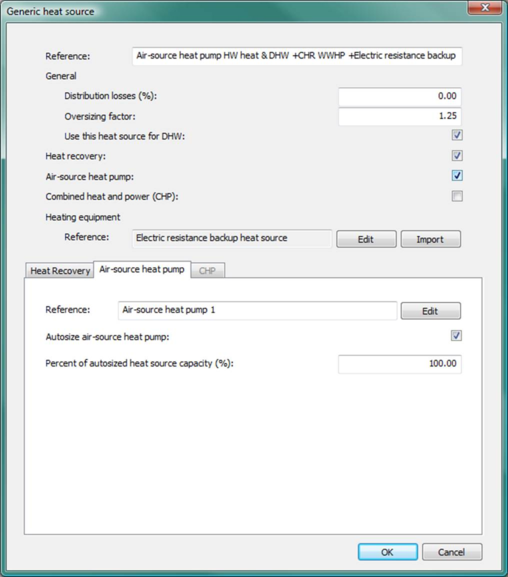
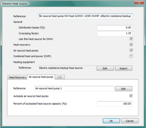
Figure 3 - 3 : Generic heat source (GHS) editing dialog showing illustrative inputs for a model combining an autosizable air-source heat pump as the primary heat source for both space-conditioning and domestic hot water (DHW), heat recovery, and an electric resistance back-up heat source.
GHS Reference name
Enter a description of the component. The reference is limited to 100 characters. It is for your use when selecting, organizing, and referencing any component or controllers within other component and controller dialogs and in the component browser tree. These references can be valuable in organizing and navigating the system and when the system model is later re-used on another project or passed on to another modeler. Reference names should be informative with respect to differentiating similar equipment, components, and controllers.
Heating equipment
The Heating equipment Reference displays the name of the associated part load curve heating plant.
The Part load curve heating plant component of a generic heat source can be defined in two ways:
1) Clicking Edit just to the right of this field and specifying parameters and performance data in the part load curve heating plant dialog;
2) Clicking the Import button to the right of this field and selecting part load curve heating equipment to copy from another heat source or water loop. The Import facility list existing heat sources, each of which can be expanded in the tree to show associated heating equipment that can be selected for importing. A copy of the selected heating equipment is added to the currently open Generic heat source and its reference name displayed in the Heating equipment textbox. Note that only Part load curve heating equipment can be imported to a Generic heat source.
The selected Heating equipment is, of course, also editable via the Part load curve heating plant dialog that is opened via the Edit button to the right of this field.
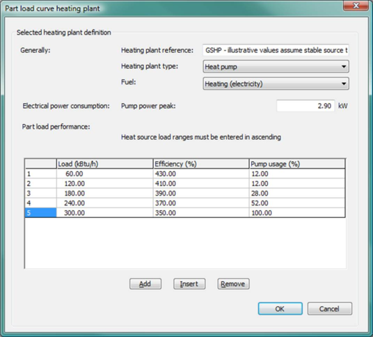
Figure 3 - 4 : An illustrative Part load curve heating plant dialog. Parameters and inputs for this dialog are explained in section 2.5, following the Hot Water Loop and Heating Equipment Sequencing section.
Distribution Losses
Enter the losses due to heat distribution as a percentage of heating load. For example, if distribution losses are entered as 5% and the heat source is connected to 10 radiators presenting a total design heating load of 20kW, the distribution loss of 0.05 × 20 kW (1kW) is added to radiator heat demand to give a fuel consumption of 21 kW × the heating plant efficiency at the design load. The losses, however, do not accrue to zones in the building; they are assumed to be losses to outdoor or unconditioned spaces.
Oversizing factor
This is the factor by which the heating plant size is increased relative to the peak load in the design sizing run. This is applied immediately following the System-level autosizing step that runs the ApacheHVAC system under heating and cooling design conditions via ASHRAE Loads.
Use this heat source for DHW?
Tick this box to designate this GHS to serve Domestic Hot Water (DHW) loads (otherwise sometimes referred to as “service hot water”). You must also tick the Is DHW served by ApacheHVAC boiler? checkbox in the Hot water tab for the Apache system that is used to simulate DHW loads, storage tanks, and dedicated solar-DHW systems in Apache Thermal view. This second step will pass the heating loads to the designated Heat source in ApacheHVAC.
Heat recovery
Heat recovery—most often, but not always, from a condenser water loop for cooling equipment, and in this case referred to as condenser heat recovery (CHR)—is permitted to serve heating loads ahead of any other heat sources within the overall GHS dialog. As previously noted, the hard-wired sequence for serving loads with a Generic heat source is CHR à ASHP à CHP à Part load curve heating plant .
There are two heat recovery heat exchanger and water-source heat pump model options for Hot water loops; however, only the simpler fixed-percentage maximum effectiveness heat exchanger and fixed-COP water-to-water heat pump are available for use with Generic heat sources, as these heat sources do not include explicit modeling of the loop water temperature:
-
Percentage of heat rejection heat-exchanger model
This simple heat-exchanger model is essentially the same as the heat recovery model provided in pre-v6.5 versions. It models the heat recovery as a simple percentage of the source heat rejection. The percentage represents a fixed heat-exchanger effectiveness.
-
Fixed-COP water-source heat pump model
The temperature for the recovered heat can be upgraded with a water-to-water or water-source heat pump (WSHP)—e.g., from 90°F to 140°F. This would typically be used when serving space-heating loads such as direct (DX-based) heating of supply air or hot water for heating coils and baseboard heaters that require higher temperatures than normally available via a simple heat exchanger on the condenser water loop. The Percentage of heat rejection model can be used regardless of whether there is an explicit modeling of the loop water temperatures on the heat recovery source and recipient sides.
Capacity for the simple WWHP (or WSHP) for Heat Recovery is now limited to a user-specified percentage of the heat recovery source capacity, while in pre-v6.5 versions the WWHP capacity is limited by a dynamic limit specified as a percentage of the instantaneous load on the source. The reason for this enhancement is that limiting the WWHP capacity by a fixed finite capacity is more realistic than a dynamic limit, such that users can avoid recovering more heat with the WWHP than would be possible (or desirable) in practice. Without this constraint the WWHP could entirely displace the boilers on a HWL, which might not be what the user intends or expects.
Heat recovery sources and recipients
All heat recovery data are now displayed, edited, and stored on the recipient side ( Figure 3-5 , below).
Heat recovery sources can be either a part-load-curve “chiller” model (which may represent something other than a water-cooled chiller) or a condenser water loop serving one or more electric water-cooled chillers. Future versions will expand on the range of possible sources, for example, allowing the heat-transfer loop to be selected as a source. Heat recovery recipients can be a generic heat source, a hot water loop, or a heat transfer loop.
When Percentage of heat rejection model is used (the only options available with the Generic heat source as recipient), there can be multiple heat recovery sources linked to one recipient. This is among the reasons that the sources are now specified in the recipient dialog. Source types can be any combination of condenser water loops and/or part-load curve chiller models. Each heat recovery source can be linked to just one heat recipient.
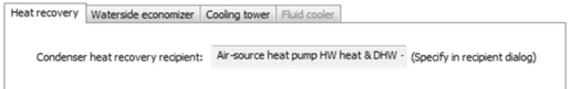
The heat recovery recipient is displayed on the source side (Heat recovery sub-tab within the Heat Rejection tab of the Chilled water loop dialog and in the Part-load curve chiller model dialog) for user’s information only.
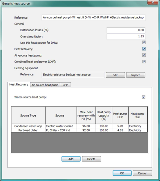
Figure 3 - 5 : Heat Recovery tab within the Generic Heat Source dialog (top) with water-to-water heat pump and illustrative selection of heat recovery sources, percentage availability/effectiveness, capacity relative to source loop, and WWHP COP for each source. Also shown (below GHS dialog), the Condenser heat recovery recipient designation is displayed within the Heat rejection tab of the Chilled water loop dialog.
Heat recovery checkbox and tab
Tick this checkbox to specify Heat recovery as a heat source on the generic heat source (GHS). Ticking or un-ticking this checkbox will enable or disable the associated Heat recovery sub-tab below.
When the Heat recovery sub-tab is active, you will be able to specify multiple heat recovery sources in a source table, together with other parameters required by the Percentage of heat rejection model. (Note that the only heat recovery model available here is the Percentage of heat rejection model, as there is no explicit modeling of loop water temperatures in the case of a Generic heat source.)
For each row in the heat recovery source table, the following column fields are displayed:
-
Source type —condenser water loop or part-load chiller model
-
Source —a particular loop or part-load chiller model
-
Max. heat recovery with HX (%) —i.e., as percentage of source loop load
-
Heat pump capacity (%) —i.e, as percentage of source loop capacity
-
Heat pump COP —fixed in the case of the simple Percentage of heat rejection model
-
Heat pump fuel —energy source type
A heat recovery source can be added or removed using the Add or Delete button below the source table. Double clicking any active cell within the source table provides editing access to that specific cell.
Water-source heat pump checkbox
The heat recovered from the heat recovery source(s) may be upgraded using a water-source heat pump (See additional explanation in section 2.3.3, above). Specify this mode of operation by ticking the Water-source heat pump checkbox.
Source type
Choose the heat recovery source type for a particular source—condenser water loop or part-load chiller model. Double clicking in this column of the source table allows you to choose from two options: Condenser water loop or Part-load chiller (more options, such as heat transfer loop, to be added).
Source
Choose the particular heat recovery source of the selected type by double-clicking the cell in this column and picking the source name from those available. Heat recovery sources previously assigned to other recipients will not be shown on this list.
Sources that will be available in the dropdown list:
· If the selected Source type is Condenser water loop, the drop-down will list all available chilled water loop names in the system file. The defined chilled water loop must have a condenser water loop (the Condenser water loop checkbox in its Heat rejection tab is ticked), which has not been specified as one of the heat recovery sources of any other heat recovery recipient.
· If the selected Source type is Part-load chiller, the drop-down will list all available Part-load chiller names in the system file. Available Part-load chiller models will include all those defined in the system file that have not been specified as a heat recovery sources for any other recipient.
For each source, the associated recipient will be displayed (for information only) in the corresponding source dialog. For example, when a particular Condenser water loop is specified as a source, the Heat recovery sub-tab within the Heat rejection tab of a Chilled water loop dialog will list the recipient.
Max. heat recovery with HX (%)
This column of the source table allows setting the percentage of the source heat rejection that is subject to heat recovery using a heat exchanger or water-source heat pump.
For the Percentage of heat rejection model , the amount of heat recovered at any given time is given by:
Where
Ql is the load on the cooling equipment (the load on one or more electric water-cooled chillers in a chiller set, if the heat recovery source is a condenser water loop; the load on the named part-load curve chiller, if the source is set to Part-load chiller).
Qc is the compressor power for the chiller(s).
p is heat recovery percentage—equivalent to a fixed heat exchanger effectiveness.
Heat pump capacity (%)
When the water-source heat pump option is active (checkbox is ticked), this column of the source table allows for setting its capacity. Enter the capacity for the heat pump as a percentage of the source loop capacity. This is used to limit the capacity of the water-source heat pump. For example, when the heat recovery source is a condenser water loop, the source loop capacity is the cooling tower or fluid cooler capacity (thus the condenser water loop heat rejection capacity). When the heat recovery source is a part load chiller, the source loop capacity is the heat rejection capacity for that device, which is maximum part-load chiller.
Heat pump COP
When the water-source heat pump option is active (checkbox is ticked), this column of the source table allows for setting a fixed heat pump COP associated with a particular heat recovery source. This should normally be the heat pump COP when the source loop and recipient loop are at design temperatures; however, this may differ for some system designs.
Heat pump fuel
When the water-source heat pump option is active (checkbox is ticked), this column of the source table allows for setting the heat pump fuel code or type of energy source. For scratch-built systems, this will normally be Electricity and for pre-defined systems this is set to Heating (electricity), which is an end-use designation for the ASHRAE 90.1 Performance Rating Method reports.
Air-source heat pump
An Air-source heat pump (ASHP) can be included as a component of the Generic heat source. This can b e used to model an ASHP as the primary heat source for both space heating and domestic hot water when the backup heat source is intentionally sized smaller than the peak load. This is in contrast to the modeling of an ASHP on a HW loop, wherein the HW loop flow rate is determined by the total capacity of boilers and/or other part-load curve equipment in the Heating equipment set. The ASHP in the Generic Heat sources dialog has otherwise been implemented to cover heat pumps in legacy systems from older versions of ApacheHVAC. It can be used to model either an air-to-water heat pump (as can be modeled for pre-heating on a Hot water loop) or an air-to-air heat pump (AAHP). However, the latter is normally done via the separate AAHP Types dialog, wherein types are defined and a new instance of each type is created for each heating coil assigned (AAHPs normally have a one-to-one relationship with the heating coil they serve). When present, the Air-source heat pump will be the first in line after condenser heat recovery (when active) to meet assigned loads.
The following loading sequence is pre-set for all Generic heat sources: CHR à ASHP à CHP à Part load curve Heating equipment .
The air-source heat pump option within the Generic Heat Source dialog is activated by a tick box and is accessed via a tab in the lower part of the dialog.
Figure 3 - 6 : Generic heat source dialog (shown with the Air-source heat pump sub-tab selected).
Air-source heat pump
Tick this checkbox to specify an air-source heat pump as part the Genetic heat source. The input parameters for Air-source heat pumps are described in section 3.6.2 These parameters are accessed for editing by clicking the Edit button in then Air-source heat pump tab.
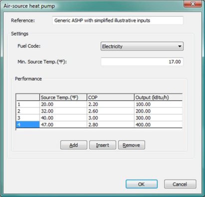
Figure 3 - 7 : Air-source heat pump dialog with illustrative inputs (described in section 3.6.2 ).
Air-source heat pump reference
This displays the reference name of the Air-source heat pump associated with this Generic heat source.
Autosize air-source heat pump
Tick this checkbox to autosize the associated air-source heat pump during a system sizing run.
When this box is ticked, the peak required Generic heat source capacity determined by autosizing will be multiplied by the Percent of autosized heat source capacity (%) (see below) to determine the Air-source heat pump capacity. The resultant maximum heat pump capacity value will then be used to update the part-load air-source heat pump capacity values as with air-to-air heat pumps (the autosizing will reset the value in the bottom row and proportionally adjust all other values to maintain their relationships).
Note that the autosized capacity of the Air-source heat pump is not subtracted from the overall Generic heat source capacity. The size of the Air-source heat pump size will not influence the size of the Part load curve Heating equipment component of the Generic heat source.
Percent of autosized heat source capacity (%)
During a system sizing run, if the Autosize air-source heat pump? checkbox (see above) is ticked, the sized Generic heat source capacity will be multiplied by the value in this field to set the Air-source heat pump capacity. The resultant maximum heat pump capacity value will then be used to update the part-load capacity (output) values in the Air-source heat pump dialog: The autosizing will reset the value in the bottom row and proportionally adjust all other values to maintain their relationships as load fractions.
Once the generic heat source has been sized, edits made in this field will dynamically update the capacity of the Air-source heat pump, adjusting of all part-load Output values in the associated heat pump dialog to maintain their proportional relationships to the value in the bottom row.
The autosized capacity fraction assigned to the Air-source heat pump is not subtracted from the overall Generic heat source capacity. In other words, the sizing of the Air-source heat pump size does not alter the size of the Part load curve Heating equipment component of the Generic heat source.`
Combined Heat & Power
Heat available from a Combined heat and power (CHP) system can be used as a heat source on the generic heat source. When present, heat available from the CHP system will be used to cover the load imposed on the generic heat source, prior to engaging the part-load curve Heating equipment, according to the following loading sequence: CHR à ASHP à CHP à Part load curve Heating equipment . A CHP system is defined within the CHP section of the Renewables dialog in the Apache Thermal view.
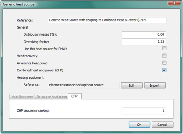
Figure 3 - 8 : Generic heat source dialog (shown with the CHP sub-tab selected).
Combined heat and power (CHP)
Tick this box to indicate that loads served by this heat source will be met by available heat from a Combined heat & power (CHP) system prior to engaging the part-load curve Heating equipment. When present, heat available from CHP will be used to cover the load imposed on the generic heat source according to the following loading sequence: CHR à ASHP à CHP à Part load curve Heating equipment . A CHP system is defined within the CHP section of the Renewables dialog in the Apache Thermal view.
CHP sequence ranking
CHP sequence ranking determines the sequence in which heat available from CHP are used to cover heating loads imposed on the specified heat sources. Heat sources (Generic, Hot water loop, or Heat transfer loop) with lower values of this parameter will receive available heat from CHP before those with higher values. If two ApacheHVAC heat sources have the same sequence ranking in this field, they will simultaneously receive available heat from the CHP system defined under Renewables in the Apache Thermal view until either the loads are met or the CHP resource is fully utilized.