Editing a Glazed Project Construction
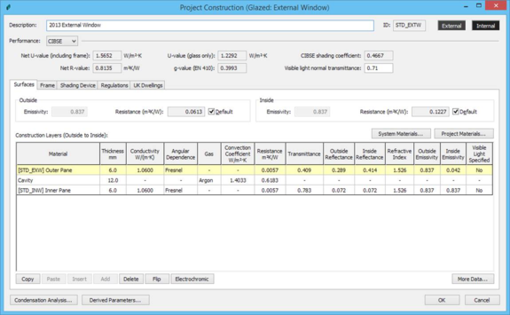
This dialog appears when a glazed project construction is selected for editing by means of a double click or the Edit selected construction icon. It displays the properties of a glazed construction and allows them to be edited. The dialog includes tabbed sections, as shown below:
Figure 8 Glazed construction
All transparent constructions of whatever material, including transparent doors, should be defined as glazed constructions.
The fields and buttons displayed on the dialog are described below. Fields appearing on a white background are editable. When setting this data it is important to understand the conventions applied to the orientation of constructions and the ordering of their layers, which are described in the section headed Construction orientation.
Description: a description of the construction in words.
ID: a unique identifier assigned to the construction when it is created.
External: Shows the colour used by Radiance for the internal surface when this construction is assigned. When clicked, displays a colour picker allowing the assigned colour to be changed.
Internal: Shows the colour used by Radiance for the internal surface when this construction is assigned. When clicked, displays a colour picker allowing the assigned colour to be changed.
Performance: The type of U-value calculation used (CIBSE, EN-ISO or ASHRAE). Note that the EN-ISO method does not take account of the entered values for emissivity, surface resistance or wind exposure.
Net U-value (including frame): the net U-value of the construction, calculated as an average of the centre-pane and frame U-values, weighted according to the frame percentage. Calculated using the selected method (CIBSE, EN-ISO or ASHRAE).
U-value (glass only): the centre-pane U-value of the construction, calculated using the selected method (CIBSE, EN-ISO or ASHRAE).
CIBSE shading coefficient: The ratio of the instantaneous heat gain at normal incidence transmitted by a particular glass/blind combination to that transmitted by a reference glass, usually 3 mm or 4 mm thick clear glass. See CIBSE Guide A section5.
Net R-value: total thermal resistance of all the glazed layers (including surface resistances).
g-value (BS EN 410): the solar transmittance (between 0 and 1)
Visible light normal transmittance: the proportion of normally incident visible light that is transmitted by the glazed portion of the construction.
Surfaces Tab
Outside surface:
Emissivity: the emissivity of the outside surface of the construction. If the construction involves low-emissivity coatings these are usually applied to surfaces facing into an air gap, and do not therefore affect the outside or inside surface emissivities. If the outer pane has an emissivity for its outside surface, this sets the construction outside surface emissivity automatically.
Resistance: the thermal resistance between the outside surface and its environment. This is the reciprocal of the outside heat transfer coefficient, which is made up of convective and radiative components. Ticking the default box displays a standard value determined from the construction category and, in the case of external adjacency, the Wind exposure. The displayed default value is used in the ApacheCalc programs. In ApacheSim it is replaced by algorithms that take account of the changing heat transfer conditions at every time step. If the default box is not ticked, the entered value is used by all programs.
Inside surface:
Emissivity: the emissivity of the inside surface of the construction. If the construction involves low-emissivity coatings these are usually applied to surfaces facing into an air gap, and do not therefore affect the outside or inside surface emissivities. If the inner pane has an emissivity for its inside surface, this sets the construction inside surface emissivity automatically.
Resistance: the thermal resistance between the inside surface and its environment. This is the reciprocal of the inside heat transfer coefficient, which is made up of convective and radiative components. Ticking the default box displays a standard value determined from the construction category. The displayed default value is used in the ApacheCalc programs. In ApacheSim it is replaced by algorithms dependent on simulation options. If the default box is not ticked, the entered value is used by all programs.
Frame Tab
Percentage: The material percentage of the glazing element taken up by the frame. This is used in solar calculations and affects net U-value.
U-value: The U-value of this window including the frame, calculated using the selected method (CIBSE, EN-ISO or ASHRAE). U -values for various types of window frame and sash are given in CIBSE Guide A Table 3.25 and are based on data given in BS EN ISO 10077-1.
Absorptance: The absorptance of this frame. Absorptance is defined as the ratio of the amount of radiation absorbed by a surface to the amount of radiation incident upon it. Standardised values can be assumed as follows:
- dark coloured surface = 0.9
- light coloured surface = 0.5.
Resistance: The resistance of this frame. The resistance is expressed in m2K/W and is the reciprocal of thermal conductance.
Outside surface area ratio: The outside surface area ratio of this frame. This is the material percentage of the outside surface taken up by the frame.
Inside surface area ratio: The inside surface area ratio of this frame. This is the material percentage of the inside surface taken up by the frame.
Type: The type of frame material selected from a list. The list includes softwood, hardwood, steel, aluminium, PVC and metal and this is used in UK Part L compliance testing.
LCA frame materials: The assigned list of special LCA frame materials is displayed. The Edit button displays a dialog allowing you to edit this list of special LCA frame materials to your construction. This is only relevant to users of the cost planning and life cycle software where the datasets include some special materials with quantity method set to length instead of area. These are used in LCA to account for the environmental impact or costs of frame materials.
Shading Device Tab
Local shade: Click on the question mark to specify a local shading device. See Shading devices for details.
External shade: Click on the question mark to specify an external shading device (shutter or louvre). See Shading devices for details.
Internal shade: Click on the question mark to specify an internal shading device (curtain or blind). See Shading devices for details.
Regulations Tab
This tab is only displayed if you have a licence for a relevant compliance application such as VE Compliance Part L2, Title 24 California or ASHRAE 90.1 PRM. The parameters set here are only required for special purposes (e.g. categorisation of the Construction element) in the relevant regulation.
Data Source: Generic, NCM, etc.
Surface area ratio: The surface area ratio of this window. This is the “developed area to projected area” ratio for the window or rooflight. The developed area is the total area of the glass plus the frame, and the projected area is the area of the opening in the wall/roof. Therefore, for domed or conical rooflights, for example, this ratio would be larger than 1. It cannot have a value which is less than 1.
Thermal bridging coefficient: Part L2 requires an allowance to be made for non-repeating thermal bridging. In the VE implementation this is handled via a coefficient expressing this component of heat loss as a multiple of element area. This can be thought of as an addition to element U-value. The default value is 10% of the element U-value. In the notional building, thermal bridging coefficients are set to standard values laid down in the NCM methodology document.
Window Type: The Window type option allows the user to mark the element as a glazed door for UK Building regulations u-value check categorisation or as a roof monitor for the calculation of correct ASHRAE 90.1 PRM daylight control zones.
Select from the following options
· Window: The default value for a glazed element, select this for a window or rooflight
· Personnel door: a standard glazed door.
· Vehicle access or similar large door: a category of glazed door to which special rules, including more stringent U-value requirements, are applied in the Building Regulations.
· High usage entrance door: select this option to represent a glazed entrance to a building with a high throughput of people (e.g. shopping centre, airport).
· Roof Monitor: select this to mark the window as a roof monitor, this is used for ASHRAE 90.1 PRM 2013 Navigator assignment of roof monitors to apply special daylight zone rules when calculating daylight zones for lighting controls.
BFRC Data Values: tick if you wish to add values as defined under the conventions of the British Fenestration Rating Council. If so, enter g-value and Light transmittance.
Display Window?: tick if this is a display window.
UK Dwellings Tab
These parameters are required only for dwellings under UK Building Regulations compliance testing.
Glazing type: select a glazing type.
% Sky blocked: select a category from the list to indicate the degree of shading.
Electrochromic Glazing Tab
These parameters determine the controller for an electrochromic glazed construction. This tab is only displayed if the glazed construction contains an Electrochromic layer.
Control Profile: Select a modulating profile to determine when the electrochromic glazing is active. When inactive (profile value of 0), the pane will be in its clear state. When active (profile value of 1), the pane will interpolate between the specified clear and dark states based on the value of its control function. If the profile takes a value between 0 and 1, then the control function will be weighted by the control profile..
Control Function: The control function is a formula, much like those used in formula profiles. However, the control function is different in that it stands on its own; it is not attached to a profile. When a simulation runs and the electrochromic glazed element is active, the control function (whose value, once evaluated, is clamped between 0 and 1) determines the tint of the glazing by linearly interpolating between 0 (clear) and 1 (dark). The variables that may be used in the control function are the same as those in any other function, with the addition of the incident solar irradiance variable, ii, as noted in the ApPro documentation.
The default formula in Metric is “(ii – 400.0)/400.0” (with an equivalent default for projects using imperial units). This linearly interpolates between 0 at 400W/m
2 and 1 at 800W/m
2. The syntax of the formula follows that used in ApPro for formula profiles – an indicator to the right of the text box will show whether the formula is valid (

) or invalid (

). If an invalid formula is entered, the construction window’s OK button is disabled.
Metric / Imperial: These buttons set the units of the control function variables. When the formula is evaluated, the variables are replaced by their values in whichever system of units is specified. However, switching between Metric and IP does not convert constants to the specified units. As an example, consider the default metric formula of (ii - 400.0)/400.0. At ii = 800W/m2, it evaluates to 1, if the formula is evaluated as metric. However, if it is evaluated as IP, it evaluates to -0.37 (clamped to 0 during simulation) because 800W/m2 is the same as 253.6Btu/(h.ft2). It is important, therefore, to consider the physical dimension of constants in an expression and convert them accordingly.
?: This button opens the ApPro user guide at the formula syntax section, for guidance on possible values that could be used for the Control Function formula.
The control signal for the layer is determined by multiplying the Control Profile by the Control Function – this will allow the true state of the Electrochromic Layer to be determined during simulation (the value will be appropriately interpolated between fully transparent and fully opaque).