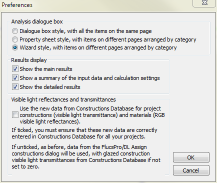
Preferences Dialogue Box
This dialogue box is displayed when you select Preferences on the Settings menu.
· Analysis dialogue box - select a style for the Analysis dialogue box – this may be displayed in one of 3 styles – a dialogue box with all the items on one page, a property sheet with 4 pages, or a “wizard” with 4 pages (equivalent to those on the property sheet). The wizard may be simpler to use for beginners but requires more mouse clicks. The dialogue box is quicker for experienced users.
· Results display - select the sections you want in the analysis results.
· Visible light reflectances and transmittances – Constructions Database now has new fields for visible light data you may wish to use instead of data you enter in the Assign constructions dialog. However, if you choose this option, you must make sure that suitable data has been entered in these fields in Constructions Database.
Analysis Dialogue Box
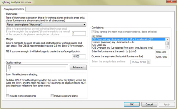
The Analysis dialogue box allows you to run an analysis calculation. It may take one of two styles, depending on the preference you have set using the Settings > Analysis option.
The first style (default) is a single-page dialogue box as shown here:
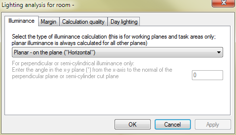
The second style is a property sheet that has 4 pages:
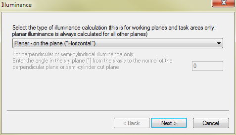
The third style is a wizard with exactly the same pages as the property sheet.
We shall only discuss the third style here. The items on the single page dialogue box and the property sheet are exactly the same, apart from the buttons at the bottom.
You may specify various calculation settings, including the sizes of the calculation grids, whether to check for obstructions, whether to include component surfaces as reflecting or obstructing components, and inter-reflection calculation method.
Note be careful how much detail you request - the calculations can be very slow if you select a fine grid, especially if you are checking for obstructions or performing a full inter-reflection calculation. When you enter data an estimate is made of memory and time required. A warning is given if either of these gets large. As a rule of thumb, perform your initial calculations with fairly coarse grids, e.g. 0.25m for working surfaces and 0.5m for all others, being the maximum coarseness allowed for CIBSE uniformity and diversity calculation purposes.
The program allows you to create working surfaces or task areas. However, a default horizontal working surface is always automatically created at the specified working surface height, and bounded by a boundary polygon inset 0.5m from the cross section of the room when cut by the plane. A task area is created at the geometric centre of this default working plane. (A later version may allow you, after the calculations, to examine any sub-area of a working plane as if it were a task area.)
Back Button
Press this to go back to the previous page in the Wizard.
Next Button
Press this to go forward to the next page in the Wizard.
Finish Button
Press this to start the calculations. The Progress dialogue box will now display, where the calculation may be monitored (in multi-room mode, the Progress dialogue box is displayed for each room in turn).
Cancel Button
Press this to abandon the calculations.
Illuminance Page
Illuminance Type
Specify the type of illuminance to calculate for working planes and task areas. Note all other surfaces always use Planar illuminance:
· Planar (“horizontal”). This is the simple illuminance on the receiving plane. Usually this is a horizontal plane, hence the term “horizontal”.
· Perpendicular (“vertical”). This is the illuminance on a plane passing through the point and perpendicular to the receiving plane. Typically the latter is a horizontal plane, hence the term “vertical”. It is used mainly for environments where there are many vertical surfaces to be illuminated, mostly facing in the same direction, e.g. a control room with many display terminals.
· Cylindrical. This is the average illuminance over the surface of a cylinder whose axis passes through the point and is perpendicular to the receiving plane. Effectively this means that only the component of the incidence angle parallel to the cylinder axis is taken into account.
· Semi-cylindrical. Similar to cylindrical illuminance, but the cylinder is cut in half by a plane parallel to its axis. This means it is treated in the same way as cylindrical illuminance, except that there is a cut-off when the component of the incidence angle perpendicular to the cylinder axis exceeds +/- 90 degrees.
· Scalar. This is the average illuminance over the surface of a sphere.
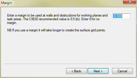
Margin Page
Working Surface Margin
Enter the margin to be left uncalculated at the edges of working surfaces. Because the grid size is constant, the calculations will be inaccurate when the working surface is close to a room surface. The CIBSE-recommended margin is 0.5m.
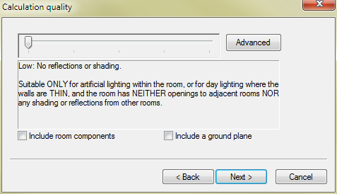
Calculation Quality Page
Quality slider
Use this to select from a number of predetermined quality settings. The text below will change as you move the slider to give you more detail about the quality setting. Please use this to confirm whether the quality you have chosen will be adequate for the purpose. If in doubt, use the Advanced button to set the quality at a higher level of detail.
Advanced button
This will show the Advanced Quality Settings dialogue box, where you can set the calculation quality at a higher level of detail.
Include room components toggle button
Select this if you have placed components in the room, and you need these to be taken into account in the lighting calculations.
Include a ground plane toggle button
Select this if you wish a ground plane to be included in the calculation. This is a notional ground plane created at z=0 around the building. Include it if you wish to determine whether any extra light may be available due to reflections off the ground. NB the reflectance is assumed to be 10%. Also this is only meaningful if you are using full inter-reflection calculations.
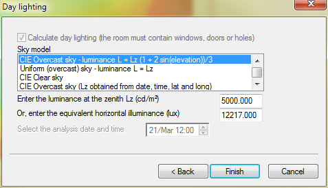
Day Lighting Page
This page is only available when the room contains windows or a multi-room calculation is being performed.
Calculate Day Lighting Toggle Button
Select this to calculate day lighting from all the external openings within the room. External reflections, including ground reflectance, or external obstructions, may be included if you select the correct quality settings.
Sky model
Select the sky model to use - the CIE Overcast sky, the Uniform overcast sky, the CIE Clear sky, or the CIE Overcast sky with Lz obtained from date/time. The first two are defined as functions of the value of Zenith Luminance, Lz, entered below. The last two do not need these values – instead it is a function of latitude, longitude, date and time. The latitude and longitude may be set in the Settings->Location… menu option. The date and time must be selected below.
Zenith Luminance
Enter the zenith luminance Lz of the sky model. The luminance Lγ,a at elevation γ and azimuth a is given by:
· For the CIE Standard Overcast Sky : Lγ,a = Lz (1 + 2 sin(γ))/3
· For the Uniform Overcast Sky : Lγ,a = Lz
· The next field will be calculated automatically if you enter a value here.
Equivalent Illuminance on the Horizontal Plane
Enter the equivalent unobstructed illuminance that is required on the horizontal plane. The previous field will be calculated automatically if you enter a value here. You may use this option, for example, if you wish to do a direct comparison with a Radiance calculation using the 10k CIE Standard Overcast Sky.
Date and time
This is needed if you select the CIE Clear sky or CIE Overcast sky with Lz obtained from date/time. Select the date either by selecting the day or month text and entering the text or using the spin buttons.
This allows you to select a day of the month or scroll to other months using the arrows.
Select the time by selecting the hour or minute text and entering the text or using the spin buttons.
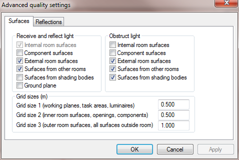
Advanced quality settings Dialogue Box
This has two pages, the Surfaces page and the Reflections page.
Surfaces page
Receive and reflect light Toggle Buttons
Select the surfaces that you wish to be included in the calculation as surfaces that receive light and can therefore also be included in the inter-reflection calculations.
Obstruct light Toggle Buttons
Select the surfaces that you wish to be included in the calculation as surfaces that obstruct light and can therefore contribute to shading.
Internal room surfaces
These are the internal surfaces of the room being calculated. They always receive light (so the “Receive light” button is always on and disabled). For a room where the internal surfaces are “concave”, e.g. inner partitions or parts of an L-shaped room, it may also be important to turn on the “Obstruct light” button.
In the room for which the calculation is being carried out (the subject room), daylight only enters via windows and holes, whether or not this check box is set. This is mainly for efficiency reasons, but effectively it means that the wall containing the window or hole is always treated as an obstructing surface for day light entering via that window or hole. So, unless other rooms are to be included in the calculation, the only reason for setting this check box would be to take account of extra obstructing surfaces, e.g. in an L-shaped room.
However, in other rooms, if they are included in the calculation, internal room surfaces are treated as obstructing surfaces only if this check box is set. So, if other rooms are included in the calculation, and there is a chance that light from internal surfaces of those rooms may contribute by inter-reflection to the subject room, this check box should be set.
Component surfaces
These are the surfaces of components that have been placed within the room. Note that it is possible to place components within a room and then move them outside. Turn the relevant buttons on if room component surfaces are to be included as sources of reflected light or as obstructions to light. Both these buttons will increase the calculation times. If the “Reflect light” button is turned on, the surfaces will also be included in the illumination calculations, and the illumination levels can therefore be viewed after the calculation. NB only components with less than 10 constituent bodies will be used.
External room surfaces
These are the external surfaces of the room being calculated. One reason for turning on the “Obstruct light” button may be to take into account the extra obstruction due to deep window recesses.
Surfaces from other rooms
These are the internal and external surfaces of other rooms, apart from the room being calculated. One reason for turning on the buttons may be to take into account reflections or shading due to nearby rooms.
Surfaces from obstructions file
These are the internal and external surfaces of rooms in any attached obstructions file. One reason for turning on the buttons may be to take into account shading due to nearby buildings, e.g. in a “right-to-light” analysis.
Ground plane
This is a notional ground plane created at z=0 around the building. Include it if you wish to determine whether any extra light may be available due to reflections off the ground. There is no “Obstruct light” button. NB the reflectance is assumed to be 10%. Also this is only meaningful if you are using full inter-reflection calculations.
Grid Size 1 for Working Planes, Task Areas and Luminaires
Enter the grid size in metres for the working surfaces and task areas. This will also be applied to luminaires if they are to be divided up into smaller light sources. NB a smaller grid size will be used if necessary for small surface areas.
Grid Size 2 for Internal Room Surfaces and Component Surfaces
Enter the grid size in metres for all other surfaces within the room apart from working surfaces and task areas. This would normally be larger than the first grid size. NB a smaller grid size will be used if necessary for small surface areas.
Grid Size 3 for External Surfaces
Enter the grid size in metres for all surfaces outside the room. This would normally be larger than the other two grid sizes. NB a smaller grid size will be used if necessary for small surface areas.
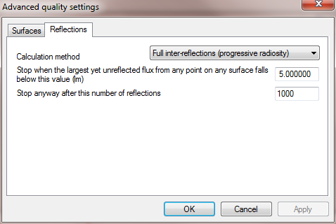
Reflections Page
Calculation Method Combo
Select the type of inter-reflectance calculation required:
· No inter-reflections – no inter-reflection calculation will be performed.
· Average inter-reflections – the average illuminance on all the surfaces in the room is reflected infinitely using the average area-weighted surface reflectance and this reflected light is assumed to be reflected evenly to all the surfaces in the room. If the average surface reflectance is R and the average initial illuminance on the surfaces is I, the infinite series of reflections of I is given by I (R + R2 + R3 + ...) which simplifies to I R/(1-R).
· Full inter-reflections (progressive radiosity). This option progressively takes the surface patch, whose as-yet unreflected flux is largest, reflects this flux to all the other room surfaces, notes it as now having been reflected, and repeats this process until there are no patches with unreflected flux above a minimum value or until the maximum number of reflections has been performed. The value of the largest remaining unreflected flux, and the number of shoots, are displayed in the progress dialogue box so that you can monitor the convergence of the calculation. The display of illuminance levels in the view is updated after every 50 reflections. You may interrupt or cancel the calculation at any stage, e.g. when you feel the calculation has begun to converge. If this option is selected, you must enter values in the next two boxes also.
Minimum Patch Flux for Reflection
Enter the minimum value of unreflected flux for a surface patch to be used as a source of reflections in the progressive radiosity calculation. The calculation will be limited by this minimum flux, by the maximum number of reflections entered below, and by any interruption you make using the Cancel button on the Progress dialogue box.
Maximum Number of Reflections
Enter the maximum number of reflections to be used in the progressive radiosity calculation. The calculation will be limited by this maximum number of reflections, by the minimum flux entered above, and by any interruption you make using the Cancel button on the Progress dialogue box.
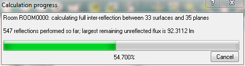
Progress Dialogue Box
This dialogue box shows you the progress of the analysis calculations. The text displays information about the current calculation phase, while the progress bar and the text below display the percentage progress. You may press the Cancel button at any time - if so you will be asked if you really wish to cancel. The screen will be updated periodically to show the latest results. This can be useful when you are performing the full progressive radiosity inter-reflection calculation.
Progress Caption
This text tells you what phase of the calculations is currently being performed.
Progress Status
This gives extra information about the part of the calculations currently being performed.
Progress Bar
This gives a visual indication of progress during the calculations.
Progress Percent
This gives the percentage progress during the calculations.
Cancel Button
Press this to abandon the calculations.
When the calculation finishes, the results are shown in the Analysis results viewer.
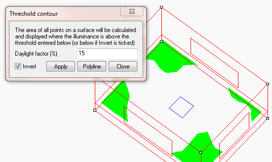
Daylight Threshold Dialogue Box
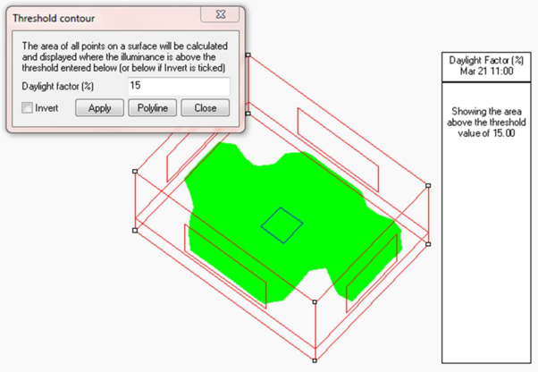
This is not available when you are displaying luminance. It allows you to set a threshold (for daylight factor or illuminance, depending on the display setting), which will then be displayed as a contour. The region where the daylight factor is above or below the contour will be shaded, depending on whether you wish to invert the shading. The threshold value and the area of the shaded region are also reported in the analysis results and in the viewport when at surface level only.
Value
Enter the value of the daylight factor threshold in percent, or illuminance.
Invert Button
Turn this on to shade the area where the daylight factor is below the threshold, or off to shade the area where it is above the threshold. The following diagram shows the effect of turning this button on:
Apply Button
Press this to update the display with the current dialogue box settings.
Polyline Button
Press this to create a DXF export of the threshold contour line. Not available at present.
Close Button
Press this to close the dialogue box.
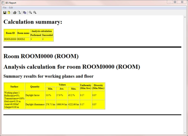
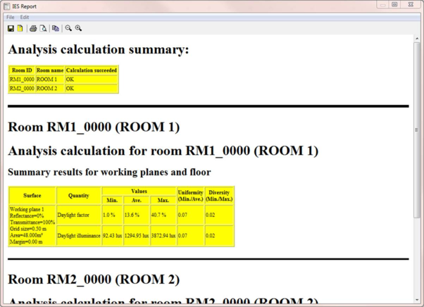
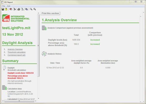
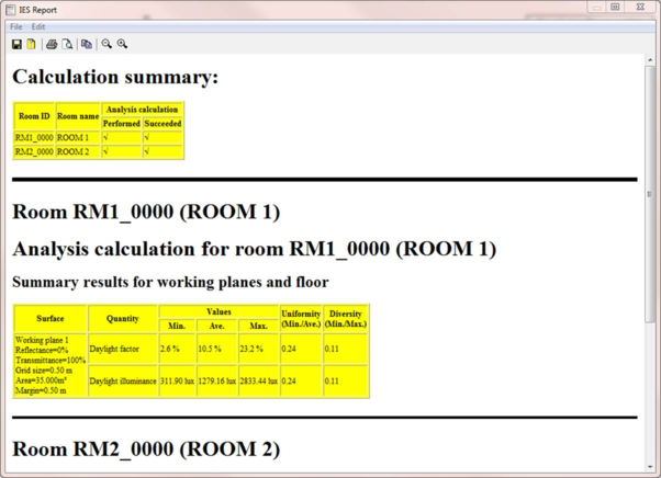
Analysis Results Viewer
This uses the IES HTML Viewer to show you a summary of the FlucsDL analysis calculations. Once again the results are displayed differently depending on the calculation mode and the results preferences:
In single-room mode, the summary results look like this:
Depending on the results preferences, a brief illumination data summary is given, just for each working plane and floor in the room. Then the input data is given, with the analysis requirements. The day lighting and inter-reflection calculations are summarised. Then an illumination data summary is given for all the illuminated room surfaces, component surfaces and working planes, and finally the detailed point-by-point results for each working plane and task area.
In multi-room mode, the results show all selected rooms and give an extra room summary table at the top so that you can see which rooms succeeded:
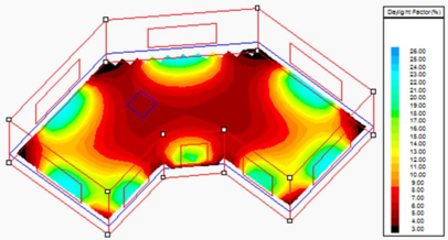
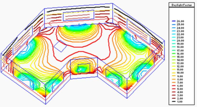
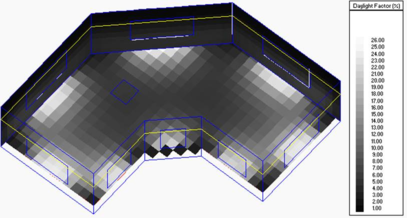
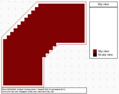
After the calculations, the levels for the selected surfaces (room surfaces, component surfaces, working planes and task areas) are shown in the view. At body level the Surface browser allows you to select different surfaces using the tick boxes. Surfaces may also be selected by clicking within their borders – and if you use the Ctrl key when clicking the existing selected surfaces are retained and surfaces whose borders enclose the point are selected cyclically. Use the various options for changing the display. The following pictures show the effect of selecting different surfaces and changing contour styles:
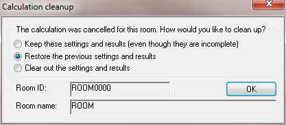
Calculation Cleanup Dialogue Box
This is displayed when you cancel an analysis calculation. It gives you the option of retaining the results calculated so far, reverting to the previous results (default), or clearing the results completely.
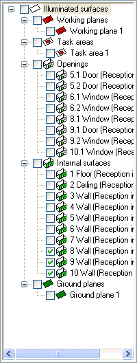
Surface Browser
At body level and in Illumination mode, the normal model browser is replaced by this Surface browser. It is also displayed but disabled at Surface level.
It shows all the illuminated surfaces after a successful Analysis calculation. This includes the default working plane and task area, any other working planes and task areas that you have added, all the internal room surfaces, and other surfaces if the relevant options for reflections were used (component surfaces, external room surfaces, other rooms, obstructions file rooms, ground plane).
You may select any one or more of the illuminated surfaces using the tick boxes. This is sometimes easier than trying to select the surfaces using the mouse, because where surfaces are overlapped in the view it is sometimes necessary to use the Ctrl button and a sequence of mouse clicks to cycle through the surfaces until the ones you wanted are selected. Tick boxes may be turned on and off by clicking individual boxes or by clicking the boxes for the “parent” categories such as “Internal surfaces”. The selected item may also be ticked on or off by pressing the space-bar on the keyboard.
When only one surface is selected you may go down to surface level and view the individual surface.
Flucs Dialogue Bar
This may be displayed at the bottom of the screen if it has been turned on using the View menu. It contains general settings for the selected room, used mainly for the design calculations. It has two pages:
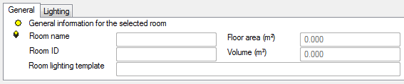
General Page
This displays read-only information derived from the selected room, a key-in box, and a prompt area.
Room Name
Displays the name that was assigned to this room.
Room ID
Displays the unique ID that was automatically generated for this room.
Floor Area
Displays the floor area of this room, calculated by the program.
Volume
Displays the volume of this room, calculated by the program.
Room Lighting Template
Displays the name of the lighting template that is currently assigned to this room. Templates are edited in the Template Manager and may be assigned when placing a room and reassigned using the Edit > Selection set > Assign Template tool.
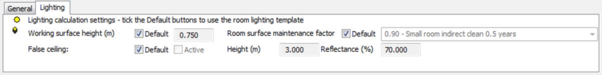
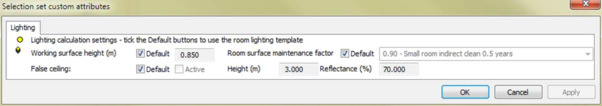
Lighting Page
This allows you to examine or over-ride the default values taken from the template for this room. These values are mainly used in the Design calculation.
Default Check Boxes
These check boxes apply to the associated item (to the right of the check box). Toggle these on to set the associated item to the default value from the template assigned to this room. Turn off to override the default value – the associated item will now be enabled allowing you to change the value.
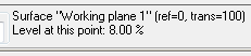
Working Surface Height
Enter the height of the working surface in metres. This is an imaginary horizontal plane used in the analysis calculation when creating the default working plane.
Room Surface Maintenance Factor
The room-surface maintenance factor is the proportion of the illuminance provided by the lighting installation in a room after a set time compared with that which occurred when the room was clean.
Typical room surface maintenance factors are shown in the CIBSE Code for Interior Lighting, 1994, Table 4.7. It is used in the analysis calculations (during the average or full inter-reflection calculations).
False ceiling active
This is used to decide whether to model an extra false ceiling in a FlucsPro/DL analysis. If you require a false ceiling to be modelled, and it is not already part of your VE model, tick this box.
False ceiling height
If an extra false ceiling is to be modeled, enter its required height above the floor.
False ceiling reflectance (%)
If an extra false ceiling is to be modeled, enter its required reflectance value.
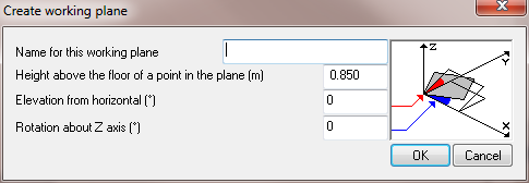
Create working Plane Dialogue Box
This is displayed when you use the tool to create a working plane, and you have specified the point that the plane passes through.
Name
Enter a name for this working plane.
Height
Enter the height of the point you have just specified.
Elevation
Enter the angle between this plane and the horizontal, in degrees.
Rotation
Enter the angle between this plane and the XZ plane, in degrees.
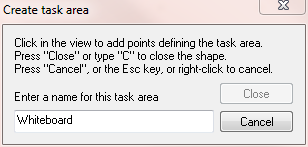
Create Task Area Dialogue Box
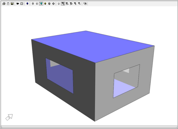
This is displayed when you use the tool to create a task area in a room surface or in a working plane at surface level. Enter a name for the task area and start specifying points by clicking in the viewport or using key-ins. When you have specified at least three points defining the task area, you may press the Close button or type “C” to close the shape and finish. You may cancel at any time by pressing the Esc key or right-clicking with the mouse.
Name
Enter a name for this task area.
Close Button
This will be enabled when at least three points have been specified. Press it to close the shape and finish.
Cancel Button
Press it to cancel creating a task area.
Custom Attributes Dialogue Box
This is displayed when you use the tool to modify the attributes for the selected rooms. It uses the same Lighting page as is used on the FlucsDL dialogue bar. Use it in the same way to override the default attributes of all the selected rooms.
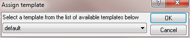
Assign Template Dialogue Box
This is displayed when you use the tool to assign a template to the selected rooms.
Select Template List Box
Select the template you wish to assign to the selected rooms.
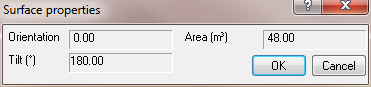
Surface Properties Dialogue Box
This is displayed when you use the use the tool to query a selected surface (at body level and surface mode, or at surface level with no openings selected).
Orientation
Shows the orientation of the surface.
Tilt
Shows the tilt of the surface.
Area
Shows the area of the surface.
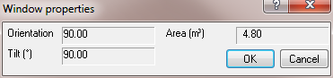
Opening Properties Dialogue Box
This is displayed when you use the use the tool to query a selected opening (at surface level with an opening selected). The appearance of the dialogue box depends on whether the opening was a door, window or just a hole:
The items are the same as for the Surface properties dialogue box.
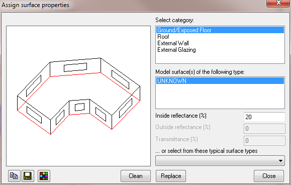
Assign surface properties dialogue box
This allows you to assign surface properties of reflectance and transmittance to surfaces within the selected room or surface.
Picture
Shows the selected room or surface. The surfaces that match the category from the Select category list box and also match the surface type from the Model surfaces of the following type list box are highlighted in the chosen highlight colour. These are the surfaces on which the Replace button will operate.
Copy button

Copies the picture to the Windows clipboard.
Save button

Saves the picture to a file.
Colours button

Opens the Surface display colours dialogue box, allowing you to set the colours for displaying the selected/not selected surfaces in the picture.
Select category list box
Shows the different categories into which the selected surfaces are organized. Select a category from this list box, and then select a surface type from the Model surfaces of the following type list box below. The matching surfaces will be shown in the picture.
Model surfaces of the following type list box
Shows the different categories into which the selected surfaces are organized. Select a category from the Select category list box, and then select a surface type from this list box. The matching surfaces will be shown in the picture.
Inside and Outside Reflectances
Enter the required reflectance or select it from the typical surface types list box and press the Replace button.
Transmittance
Only enabled for glazed elements. Enter the required transmittance or select it from the typical surface types list box and press the Replace button.
Replace button
Applies the new properties to the selected surface..
Clean button
Removes any surface type definitions from the model that were previously assigned to at least one surface but are not now (because these surfaces have now been assigned other surface types using this dialogue box). Use this after any large scale editing to retrieve any wasted space in the model.
Close button
Closes this dialogue.
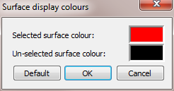
Surface display colours dialogue box
This allows you to change the colours displayed in the Assign surface properties dialogue box. Clicking either colour displays a standard Windows colour picker dialogue box where you can select a different colour. Pressing the Default button restores the default colours.
Threshold Table Dialogue Box
This is displayed when you select the Threshold table menu option or button. The values displayed depend on whether you are currently displaying illuminances or daylight factors, and also on the threshold value in the Daylight Threshold dialogue box.
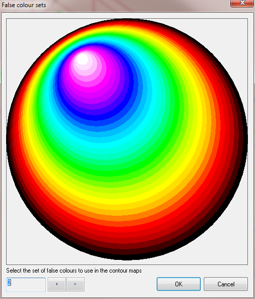
Select Colour Set Dialogue Box
This allows you to select a different false colour scheme for the contour plots.
IES HTML Viewer
This is IES’ general-purpose version of the Internet Explorer browser, used to show the calculation results. It is displayed when calculations have finished or when you use the Show Results option. Using the File menu or the Print button, you may print the current data, or save to file. Using the Edit menu, all or selected parts of the HTML may be copied to the clipboard ready to be pasted into a document.
Model Viewer
This is displayed when you use the use the Model Viewer option. The tools are the same as when called from elsewhere in <VE>.
Model dialogue bar
Key-in
Used for entering key-in commands, which are mainly concerned with the accurate positioning of coordinates instead of using the mouse, e.g. “DX=1.1,3.7”. See the <VE> documentation for details of the available commands.
Prompt area
Used for various prompts to the user while performing commands, but also to give you feedback when moving the mouse over the room surfaces after the analysis calculations.
When expected to enter a point to start creating a working plane, it prompts you to enter the point:
When no lighting calculations have been performed on the current room, it tells you this:
When lighting calculations have been performed on the current room, and the mouse is moved over a selected surface at body level and illumination mode, or at surface level, it shows the surface name and the illumination at the nearest point on the surface: