What is ConstructDXF?
ConstructDXF is used to produce data for IES’s thermal, shading analysis, lighting and building design appraisal software by scanning ordinary DXF drawings of building plan layouts, and generating a 3D building data model, within the ModelIT environment. ConstructDXF simplifies and accelerates the preparation of data for a wide range of building design studies including thermal design, shadow modelling, dynamic thermal simulation, bulk airflow analyses and electric lighting/daylighting studies.
ConstructDXF allows the generation of a full three-dimensional spatial building model and associated non-graphical attribute data from DXF format drawings.
The data model can be generated from DXF drawings containing any conventional drawing element (arcs, shapes, cells, B-splines, etc.). No special elements or attributes are required. In addition to single floor plans, ConstructDXF will cater for several buildings on one site, multi-storey buildings, and buildings that bifurcate as they rise up.
Once the 3D model has been created by ConstructDXF, geometric (and attribute) modifications or additions can be made to the model if required using the standard ModelIT facilities. Likewise, models created using ModelIT can be built further using ConstructDXF (if, for example, you wish to generate an additional storey from a DXF drawing).
Additionally, luminaires can be placed and modified in the 3D model either directly (for subsequent point-by-point analysis by the lighting calculation software) or as a result of performing a lighting design with the lighting software.
How ConstructDXF Works
The use of ConstructDXF can be broken down into the following basic operations:
· ModelIT is started and a new (or existing) project is opened.
· A drawing file in DXF format is read into ModelIT.
· Defaults for the space thermal and lighting data and fabric element constructions are set by means of space templates.
· ConstructDXF is then started within ModelIT.
· Extract settings (rules and tolerances) are set, together with default storey heights for the storey to be generated, and default window and door heights.
· A 3D data model for that storey is then generated (extracted).
· If required, another DXF drawing can then be loaded into ModelIT, and further storeys can be generated.
· Within the 3D model, the data for individual spaces and elements can be modified.
· The finalised 3D data model can then be used by the IES thermal and/or lighting software for calculation purposes.
· Calculated luminaires can be added to the 3D model.
Preparation of the DXF Drawing
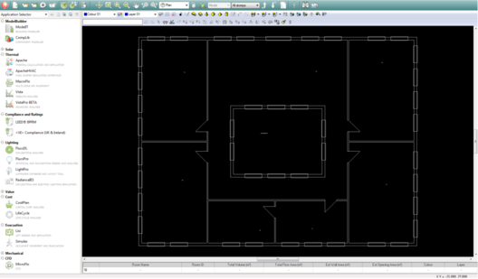
First, start ModelIT, and open a new or existing project by selecting New or Open from the File menu. Next, from the File menu, select Reference Files, and select Attach DXF File to find and attach your required DXF drawing. The DXF drawing will then be displayed in the ModelIT window.
A DXF drawing in ModelIT
Layers (levels) in the DXF file can be switched on or off within ModelIT. To do this, use the File menu and select Reference Files, then Active DXF Layers. Layers which contain elements which are not to form part of the building model (grids, dimensions, furnishing and fitting symbols, etc.) should be turned off.
ConstructDXF is designed to operate on DXF plan view drawings. If required, the same DXF file may be used for several storeys.
Drawing Elements Required by ConstructDXF
The only items in a drawing which are essential for the use of ConstructDXF are external and internal walls and space name text.
Additionally, door and window symbols (if they exist in the drawing) can be used by ConstructDXF, if you require these items in the building model.
It may be appropriate to make a copy of the original drawing, and to prepare the copy for subsequent use by ConstructDXF.
When the DXF drawing is being prepared, elements which are not to form part of the building model (such as grids, dimensions, furnishing and fitting symbols, services, drawing title blocks, etc.) should be deleted. When the drawing is initially being created, it may be easier for these items to be placed on separate layers (levels) from wall, window, door or space text elements, and then the appropriate layers can be deleted.
Stair symbols, riser symbols and hatching must be deleted. Desk partitions and partitions which do not divide a space into two separate spaces should also be deleted.
Any elements outside the building perimeter (including text) should be deleted.
Alternatively, during preparation of the DXF drawing, the unwanted items can be placed on different layers (levels) from wall, window, door or space text elements. When the DXF drawing is subsequently attached in ModelIT prior to model generation using ConstructDXF, layers (levels) in the DXF file containing unrequired elements can be switched on or off using facilities within ModelIT.
It should be noted that the best method is to delete the unwanted items or the layers containing the unwanted items. This will shorten the time taken to attach and display the drawing in ModelIT, and will also shorten refresh times when views are changed within ModelIT. The simpler the drawing, the faster ConstructDXF will generate the building model.
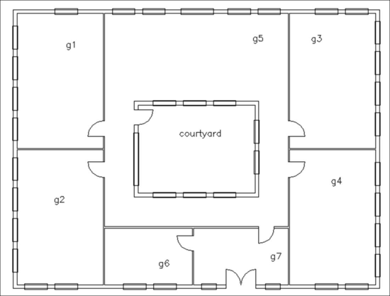
An example of a drawing containing only the required items is shown below:
Basic Rules
ConstructDXF applies three basic rules to each DXF drawing file in order to identify building perimeters, space perimeters and bordering elements including roofs, ceilings, internal floors, ground floors, external walls and internal partitions:
· Rule 1 - each building on a drawing must have a closed external loop which may incorporate door symbols and window symbols (see Window Symbols and Door Symbols below).
· Rule 2 - all internal spaces or spaces in the drawing must have a closed internal loop which may include door and window symbols (see Window Symbols and Door Symbols below). The internal loop may include some of the elements of the external loop.
· Rule 3 - all spaces to be included in the generated model must have one text label located within the space perimeter.
Wall Elements
Wall element lines should meet or slightly overlap at their intersections at internal space corners so that spaces are closed spaces, i.e. there are no breaks in the space perimeters. Similarly, wall element lines should meet or slightly overlap at their intersections at external building corners, so that the building has a closed external loop.
Note there is a facility within ConstructDXF to account for lines which do not quite intersect, but an appropriately draughted drawing will shorten the time spent using ConstructDXF.
Ideally, wall thicknesses should be comprised of one or two lines. If more than two lines are used, this may interfere with the recognition of window symbols by ConstructDXF.
Internal or external sill lines should be deleted. Hatching lines must also be deleted.
Space names
All spaces in the drawing (including internal courtyards, stairs, lifts, atria, corridors etc) to be included in the generated model should have one text label located within the space. ConstructDXF will recognise the existence of multiple labels within one space but this will significantly increase the processing time and therefore any unnecessary text should be removed.
If any spaces in the drawing do not have any text labels, then these spaces will not be included when the model is generated using ConstructDXF.
The origins of text labels must not lie within the thickness of internal or external walls.
The space text must be single line text, not multi line text.
Window Symbols
Where possible, window symbols should be placed on a separate layer (level) from other elements. When ConstructDXF is being used, a particular layer can then be specified for the identification of window symbols. If possible, windows should not have any unnecessary detail lines.
Windows should be drawn in one of two ways:
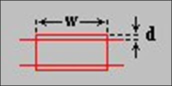
1. Elements forming an overlaid or indented rectangle within an external wall, as shown below:
w = window width
d = window offset from wall plane
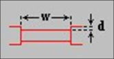
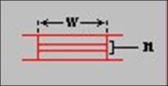
2. A number of parallel lines within an external wall element, as shown below:
w = window width
n = no. of parallel lines
Door Symbols
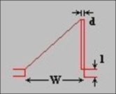
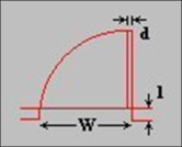
Doors may be represented using two lines at an angle of between 30 degrees and 60 degrees to each other or a 90-degree swept arc as shown below. Small line segments included within a door symbol will automatically be ignored.
d = door thickness
l = door recess depth
w = door width
Door swings must be comprised of either an arc or a single straight line. If an arc is used, it must be an arc element (i.e. the arc must not be comprised of individual straight segments). If the door symbol is comprised of any other type of element, it will not be recognised by ConstructDXF.
The door opening in the wall must not be closed off with a line, see below:
Correct Incorrect
If possible, where a 2-line wall element is being used, the door swing should connect with the inside corner of the wall element, rather than the outside corner.
Setting Up Space Templates Using the BTM
ConstructDXF uses space templates, which contain defaults for both construction and non-graphical attribute data (lighting, thermal, casual gains, air exchange, etc). The available templates are shown in the drop down list in the dialogue bar at the bottom of the ModelIT window.
Templates are created and edited using the Building Template Manager utility, which is accessed via the Templates menu on the <VE> menu bar (see the Building Template Manager User Guide for further information).
Note that you do not have to use the Building Template Manager before you generate a model. If you have no attribute information, just use the ‘default’ template. Spaces that are generated will be assigned default attributes, and you can then modify the attributes of each space individually when you have the correct attribute information.
Starting ConstructDXF
Select ConstructDXF from the Utilities menu.
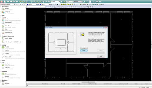
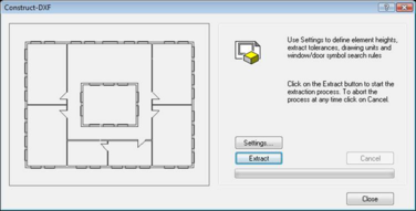
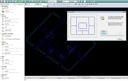
The ConstructDXF window is where extract settings are specified, and from where the model is generated.
When ConstructDXF is first started, the ConstructDXF window displays the model view which is comprised of the current DXF drawing and the 3D model (if it has been generated).
The ConstructDXF window showing the DXF drawing
Settings
Clicking on the Settings button in ConstructDXF opens the Settings dialogue box, which is split into tabbed sections.
Settings - Tolerances Tab
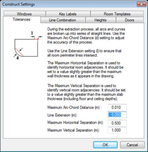
This contains controls to set various tolerances used during the model generation process.
Settings - Tolerances tab
Max Arc-Chord Distance
ConstructDXF will convert all arcs and curves into series of straight lines or vectors. The arc-chord distance is the maximum distance between the resulting vectors and the actual line. A very small arc-chord distance will result in a very accurate representation of the arc or curve but will result in a longer processing time and conversely a large arc-chord distance will produce a less accurate model but much faster processing times. Any arc having a radius within the minimum-maximum door width range will automatically be converted to a single straight line.
Line Extension
Having extracted all drawing elements from the DXF file, ConstructDXF then converts all elements into series of lines or vectors. In order to cater for drafting inaccuracies or errors in file translation, an extension may be added to the ends of all vectors to ensure that lines that should meet do actually meet. Be careful when applying extensions not to inadvertently cause lines to be joined which should be kept separate.
Maximum Horizontal Separation
This allows you to identify horizontal space adjacencies. This value should be set to slightly greater than the maximum wall thickness as it appears in the drawing.
If the distance between one space and another space (after model extraction) is less than this value, the two spaces are deemed to be adjacent to one another, i.e. the facing elements of each space are the same connecting partition.
If the distance between the two spaces is greater than the adjacency separation distance, then the two spaces are deemed to be independent of each other, i.e. the facing elements of each space are exterior walls.
Maximum Vertical Separation
This allows you to identify vertical space adjacencies. This value should be set to slightly greater than the maximum slab thickness (including floor and ceiling depths).
Settings - Line Combination Tab
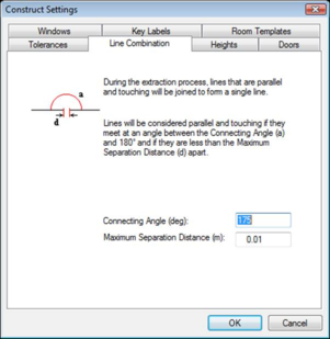
During the model generation process, any lines or vectors which are considered to be parallel and touching will be combined into a single vector. The Line Combination tab contains the tolerancing controls for determining whether or not lines should be combined.
Settings - Line Combination tab
Connecting Angle
Two lines will be considered parallel if they meet at an angle between the Connecting Angle and 180 degrees.
Max. Separation
The maximum distance between two lines, below which the lines are considered to be touching.
Settings - Heights Tab
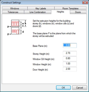
This tab is used to set default heights for the automatic model generation.
Settings - Heights tab
Base Plane
The base plane is the point in the model Z (height) plane from which the storey will be extruded.
Storey Height
The storey height is defined as the distance between the finished floor level and the finished ceiling level (i.e. the useable space height).
Window Cill Height
The default window cill height is the height of the window cills from the finished floor level.
Window Height
This is the default window height above the cill height.
Door Height
This is the default height of doors above the finished floor level.
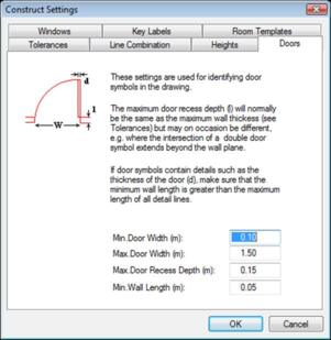
Settings - Doors Tab
This tab contains controls that are used to set tolerances for the identification of door symbols in the drawing.
Settings - Doors tab
Min. Door Width
Doors may be represented using two lines at an angle of between 30 degrees and 60 degrees to each other or a 90-degree swept arc. If the line representing the door (as opposed to the sweep) is less than the minimum door width, the symbol will not be interpreted as a door.
Max. Door Width
Doors may be represented using two lines at an angle of between 30 degrees and 60 degrees to each other or a 90-degree swept arc. If the line representing the door (as opposed to the sweep) is greater than the maximum door width, the symbol will not be interpreted as a door.
Max. Door Recess Depth
This tolerance caters for cases where the door symbol has been draughted such that the door panel line originates from one point relative to the wall (e.g. the inner surface of the wall), and where the door swing line or arc originates from another point relative to the wall (e.g. the outer surface of the wall, or within the space).
This may occur where the intersection of a double door symbol extends beyond the wall plane.
If the distance (perpendicular to the wall) between these two points is greater than the maximum door thickness, the symbol will not be interpreted as a door.
Min. Wall Length
If the length of a wall element is less than the minimum wall length, ConstructDXF will not identify this element as a wall. ConstructDXF also uses this tolerance in the identification of door elements. If door symbols contain details such as the thickness of a door, make sure that the minimum wall length is greater than the maximum length of all detail lines.
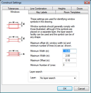
Settings - Windows Tab
This tab contains controls that are used to set tolerances for the identification of window symbols.
Window symbols are identified using the following hierarchical rules:
· Any element found on a drawing layer (level) specified in the Layer box.
· Any sequence of elements forming an overlaid or indented rectangle within an external wall.
· A number of parallel lines within an external wall element. This number must be greater than or equal to the Minimum Number of Lines setting for the identification of a window.
Settings - Windows tab
Min. Width
A window symbol will not be interpreted as a window if its width is less than the minimum window width.
Max. Width
A window symbol will not be interpreted as a window if its width is greater than the maximum window width.
Max. Offset
A window may be represented by a rectangle overlaying or indented within an external wall element. If the offset or indent of the rectangle sides from the parallel wall surfaces is greater than the maximum window offset, it will not be interpreted as a window.
Min. No of Lines
This is the minimum number of parallel lines that have to be drawn for a window element, for that element to be identified as a window.
Layer
If a drawing layer is selected for a search, ConstructDXF looks for windows on the DXF drawing layer (or level) that is selected. If you do not wish to search on other layers, select ‘No Layer Search’.
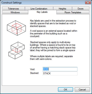
Settings - Key Labels Tab
String patterns are entered here. They are used in the extraction process to identify spaces that are to be treated as void or stacked spaces, by analysing the text in the spaces in the DXF file. Stacked spaces only apply to multi-storey models.
Settings - Key Labels tab
Void
This is used to define a search string pattern for external spaces within a building perimeter, e.g. courtyards, light-wells, etc. Any space having a name, which complies with the void space search string pattern, will be considered an external space (e.g. courtyard). The string may contain wild-card characters (* and ?). For example to include all spaces containing the string 'court', you would type in ‘*court*’. More than one key label can be defined by using a semicolon to separate the labels.
Stacked
This is used to define a search string pattern for spaces that are vertically continuous. Any space having a name, which complies with the stacked space search string pattern, will be considered a vertically stacked space (e.g. stairwell). The string may contain wild-card characters (* and ?). For example to include all spaces containing the string 'stair', you would type in ‘*stair*’. More than one key label can be defined by using a semicolon to separate the labels.
The default values set up in these Settings tabs are the result of extensive application and have been found to be appropriate for most cases. Consequently, if you are uncertain of which values to use for a drawing file, try generating a model using the default values and then modify them if necessary.
Check that the minimum/maximum door range and minimum window length and maximum window offset cover all occurrences in the drawing.
When you have entered the required data in all the above tabs, press OK to update the Settings. The Settings dialogue box will then close.
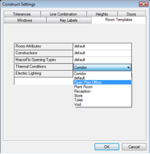
Settings – Space Templates Tab
The space templates tab lets you select which template is to be applied to all the spaces constructed from the DXF drawing. Templates allow for easy designation of common space features and conditions when constructing a <VE> model. Only one template for each category can be assigned to all the spaces during a ConstructDXF operation. More information on templates can be found in the Building Template Manager user guide.
Settings – Space Templates tab
Space Attributes Template
This section allows you to set the percentage of floor area that is lettable or circulation.
Constructions Template
This section is where the opaque and glazed constructions are specified for templates.
MacroFlo Opening Types Template
This section is where the MacroFlo opening types are assigned to templates. The opening types available are:
• Rooflight
• External Glazing
• Internal Glazing
• Door.
Thermal Conditions Template
This section is where space thermal conditions are assigned to templates. There are four tabs for thermal conditions data (five if Building Regulations are enabled):
• Building Regs (optional)
• Heating
• Cooling
• Casual Gains
• Air Exchanges
.
Electric Lighting Template
This section allows electric lighting data to be assigned to templates used by programs within the <VE> Lighting section.
Extract
Clicking on the Extract button initiates the model generation process which is displayed on a percentage completion bar. The process may be aborted at any stage by clicking on the Cancel button.
When the Extract process is complete, you will see the generated model in both the ModelIT window and in the ConstructDXF window.
A generated model
If required, another DXF drawing can then be loaded into ModelIT, and further storeys can be generated. To do this, close ConstructDXF, then use the Reference Files option from the File menu to attach the next DXF file. Then start ConstructDXF again. Before you extract the next storey, make sure that the value of the Base Plane in the Heights tab of the Settings dialogue box is equal to or greater than the Z value of the top of the current storey.
Note that you need to close the ConstructDXF window before you can use any of the ModelIT facilities.
Modifying the 3D Model
Once the model has been generated, you may use the standard ModelIT techniques to modify the thermal, lighting and construction attributes for a single space or a selected group of spaces. You may also add spaces or draw pitched roof constructions using the ModelIT drawing tools. See the ModelIT User Guide for further information.
Note that you need to close the ConstructDXF window before you can use any of the ModelIT facilities.
Use the Building option from the Settings menu in ModelIT to define the building rotation for thermal and shading calculations.
Use the APlocate utility to set up site and weather data for thermal and shading calculations (see the APlocate User Guide).
A Quick Guide to Generating a ConstructDXF Model
Create a new project by selecting ‘New’ from the File pull down menu.
Attach a DXF drawing using the Reference Files option from the File menu. Turn off all unnecessary layers in the drawing.
Start ConstructDXF. Check that the extract settings are appropriate for the current DXF file then click on the Extract button to generate the data model. The model generation progress will be displayed on a completion bar.
The process may be aborted at any stage by pressing the Cancel button.
When the extract process is complete, the generated building model data is written to a model project file with the extension *.mit. This file holds both geometric or spatial data and non-graphical attribute data.
When you close ConstructDXF, the ModelIT facilities that allow you to modify the data model are now enabled.
If required, another DXF drawing can then be loaded into ModelIT, and further storeys can be generated.