What are building elements?
A building element (often shortened to element) is a component of the building such as a wall, ceiling, floor or window. For convenience, building elements are divided into categories such as ‘External wall’, ‘Internal glazing’, etc. Where a space surface has multiple adjacencies, each adjacency is treated as a separate building element.
Two kinds of data need to be set for building elements in the Apache view: construction data describing the element’s thermal properties, and adjacency data describing its thermal boundary conditions. Construction data needs to be set for all elements. Adjacency data is set automatically as a function of building geometry, and need only be edited in special circumstances.
Construction Data
Construction types
A construction type (often shortened to construction) is a type of building element in the context of Apache thermal analysis. It consists of a layer-by-layer description of the element’s thermophysical properties, together with other data such as surface solar absorptivity and emissivity. Construction types are created and edited in the program APcdb.
The construction type attribute for a building element
Every building element has an attribute specifying its construction type. When the element is created in ModelIT, its construction type is set by the active Apache Constructions Template. This setting can later be changed using tools provided in the Apache view. The construction type attribute for an element consists of a pointer to one of the construction types defined in APcdb. This means that if the construction type data is edited in APcdb, the change immediately and automatically takes effect for all elements to which that construction type is assigned.
Changing the construction type
The mechanism for changing the construction types of building elements is as follows:
-
Select a building element or a set of building elements (this is called the selection set)
-
For the selected elements, replace all instances of one construction type with another construction type
The first operation may be done in various ways depending on the selection set required (see ‘Selecting building elements for construction type editing’).
For the second operation the usual method is to use the function ‘Edit selection set constructions’ (see ‘Changing the construction type for selected elements’). An alternative method for individual elements is to use the Query button.
The same mechanisms may be used to inspect the construction type of elements without changing them.
Selecting building elements for construction type editing
There are several ways to select a set of building elements in the Apache view.
At model or HVAC Zones level
At the model or HVAC Zones level of decomposition you may select a single space or a set of spaces by clicking in the model workspace or the model browser. (In HVAC Zones mode HVAC Zones, rather than spaces, are selected). Construction assignments apply to all the elements contained in the selected spaces or zones.
At space level
At the space level of decomposition (surface mode applies here) you may select a space surface. For the purposes of construction type setting, this selects all the elements contained in that surface.
At surface level (opening mode)
At the surface level of decomposition (opening mode) you may select a single opening or a set of openings.
At surface level (adjacency mode)
At the surface level of decomposition (adjacency mode) you may select a single adjacency.
Changing the construction type for selected elements
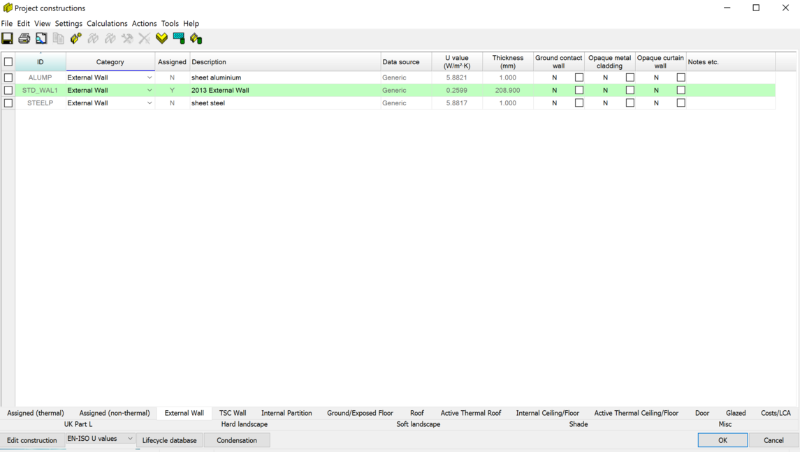
After you have selected a set of building elements you can change (or simply inspect) their construction types by clicking on the icon ‘Edit selection set constructions’ on the Edit toolbar.
Edit selection set constructions dialog (space level shown)
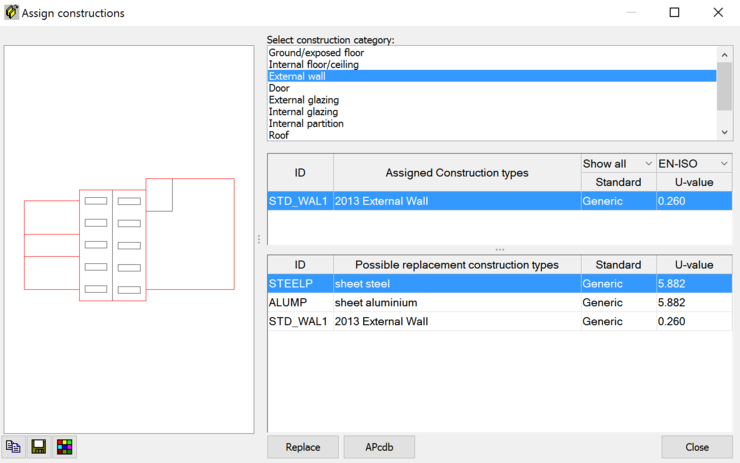
On the left of the dialog a graphic of the selection set is shown. At model and space level, the graphic uses the same view rotation as the active model window. It is usually easier to see the various elements if you select an Axonometric view in the active model window before using the ‘Edit selection set constructions’ tool.
If more than one element category is represented in the selection set it is first necessary to select one of these categories from the list headed ‘Select category’. Any edits will be applied only to elements in the selected category.
Under the heading ‘Construction Type’ you will see a list of the construction types currently assigned to the selected elements. By clicking on each construction type in turn you will be able to identify the elements where the construction is used. These elements are highlighted on the graphic.
At any stage in this inspection process you may replace all the highlighted instances of the selected construction type with another construction type. To do this, click on the desired replacement construction type in the list headed ‘Possible replacement construction types’, and then click on Replace.
If you need to create or modify construction types during this process you can run APcdb by clicking on the APcdb button.
Adjacency Data
Adjacency data for a building element describes what lies on the other side of it (when viewed from the selected space), and the assumed thermal boundary condition applying there.
Adjacency data is set automatically by the program, but in certain circumstances may be edited.
To view the adjacency data for a building element, select a space surface by clicking in the model workspace or browser, and change the decomposition mode from opening to adjacency using the selector on the model view toolbar. If the surface is adjacent to two or more spaces (including the exterior space), you will need to identify, by pointing and clicking, which adjacency you wish to interrogate.
Having selected an adjacency, click on the Query icon on the Apache toolbar to display the adjacency data.
The dialog shows the adjacent space, the area of the element, the Construction Type (which may be changed here) and the Adjacent Condition.
The Adjacent Condition is set initially depending on the category of element:
Category of element Adjacent Condition
External wall or roof Outside air
Partition wall or intermediate floor/ceiling Internal partition
Ground floor or exposed floor Outside air with offset temp. 0
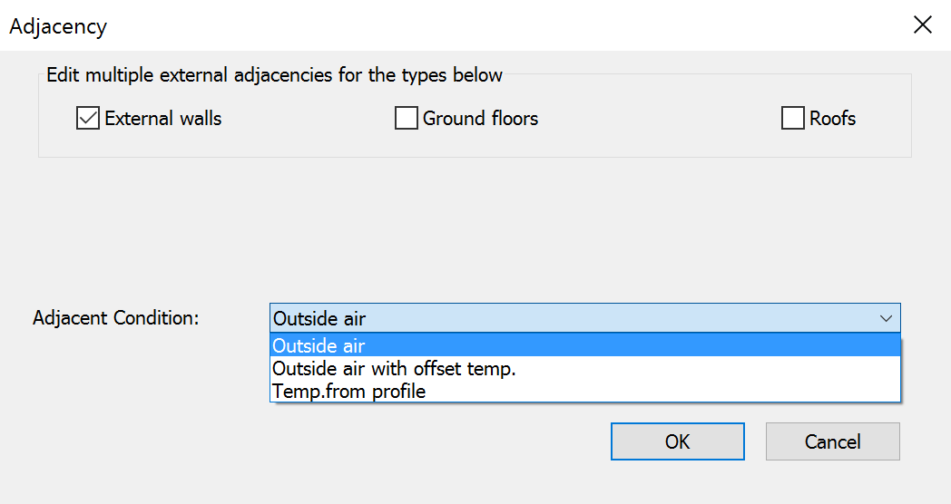
In all cases except partition wall and intermediate floor/ceiling, the Adjacency Condition may be edited. Possible Adjacency Conditions are:
· Outside air
· Outside air with offset temperature
· Temperature from profile
Outside air is self-explanatory.
Outside air with offset temperature sets the temperature on the far side of the wall to the outside air temperature plus a constant offset. Enter the value of the offset in the Temperature Offset box. This Adjacent Condition may be used to approximate a boundary condition where the external surface of the element is exposed to outside air that has been warmed by contact with the building -–for example by passing through an underground car park.
Temperature from profile allows you to set a constant or time-varying temperature boundary condition. The temperature is specified by an absolute profile created in APpro. The most common use of this feature is in the specification of temperature boundary conditions for ground floors. In the UK a ground temperature of about 13ºC may be assumed for the ground temperature at a depth of 1m. This can be modelled using a Temperature from profile Adjacent Condition with the Temperature Profile set to the system weekly profile ‘13’, a profile which has a value of 13.0 year-round.
When parts of the model (layers) are made inactive (switched OFF) they will not be included in the thermal simulations and no solar gain will be present on ceilings, floors, walls, fenestration, etc. that form an adjacency to a space that is on an inactive layer.