Baseline System Configuration (PRM System Selection Dialog) 90.1 2013
1 System Selection
90.1-2013 Section G3.1.1
Table G3.1.1-4 shows the addition of three new baseline systems:
· System no 11: Single Zone-VAV with chilled water and a choice of heating type (System 11a and 11b in ApacheHVAC)
· System no. 12: Single Zone-CV with chilled water and hot water fossil fuel boiler
· System no.13: Single Zone-CV with chilled water and electric resistance
Table G3.1.1-3 shows the new selection criteria for the HVAC systems. The following should be noted:
· The inclusion of public assembly building types
· The inclusion of retail building types
· The inclusion of the three new systems outlined above
The baseline HVAC selection dialog has been updated to include these new criteria and the PRM baseline systems have been updated to include the new systems and where appropriate make changes to existing systems to meet the 2013 standard.
While the selection dialog takes into account the selection criteria from Table G3.1.1-3 the following additional considerations should be noted when selecting the baseline system:
· Residential building types include dormitory, hotel, motel, and multifamily. Residential space types include guest rooms, living quarters, private living space, and sleeping quarters. Other building and space types are considered nonresidential. (Table G3.1.1(1))
· Where attributes make a building eligible for more than one baseline system type, use the predominant condition to determine the system type for the entire building (Table G3.1.1(2))
· For laboratory spaces with a minimum of 5,000 cfm of exhaust, use system type 5 or 7 (Table G3.1.1(3)). Note the lab exhaust fan shall be modeled as constant horsepower reflecting constant-volume stack discharge with outdoor air bypass.
· For hospitals, depending on building type, use System 5 or 7 in all climate zones (Table G3.1.1(4))
· Public assembly building types include houses of worship, auditoriums, movie theaters, performance theaters, concert halls, arenas, enclosed stadiums, ice rinks, gymnasiums, convention centers, exhibition centers, and natatoriums (Table G3.1.1(5))
· Computer rooms in buildings with a total computer room peak cooling load >3,000,000 Btu/h kW or a total computer room peak cooling load >600,000 Btu/h where the baseline HVAC system type is 7 or 8 shall use System 11. All other computer rooms shall use System 3 or 4.
It should also be noted that as per Table G3.1.10, fossil fuel systems shall be modeled using natural gas as their fuel source. This is the default in the baseline systems. The only exception is where natural gas is not available for the proposed building site as determined by the rating authority. In this case, the baseline HVAC system(s) shall be modeled using propane as their fuel source. For this case a manual update is required by the user once the baseline systems have been imported.
2 Purchased Heat / Purchased Chilled Water
90.1-2013 Section G3.1.1.1 / G3.1.1.2 / G3.1.1.3 /
G3.1.1.1 Purchased Heat For systems using purchased hot water or steam, the heating source shall be modeled as purchased hot water or steam in both the proposed and baseline building designs. Hot water or steam costs shall be based on actual utility rates, and on-site boilers, electric heat, and furnaces shall not be modeled in the baseline building design.
G3.1.1.2 Purchased Chilled Water. For systems using purchased chilled water, the cooling source shall be modeled as purchased chilled water in both the proposed and baseline building designs. Purchased chilled water costs shall be based on actual utility rates, and on-site chillers and direct expansion equipment shall not be modeled in the baseline building design.
G3.1.1.3 Baseline HVAC System Requirements for Systems Utilizing Purchased Chilled Water and/or Purchased Heat. If the proposed building design uses purchased chilled water and/or purchased heat, the following modifications to the Baseline HVAC System Types in Table G3.1.1-4 shall be used:
G3.1.1.3.1 Purchased Heat Only. If the proposed building design uses purchased heat, but does not use purchased chilled water, then Tables G3.1.1-3 and G3.1.1-4 shall be used to select the Baseline HVAC System Type and purchased heat shall be substituted for the Heating Type in Table G3.1.1-4. The same heating source shall be used in the proposed and baseline building design.
G3.1.1.3.2 Purchased Chilled Water Only. If the proposed building design uses purchased chilled water, but does not use purchased heat, then Tables G3.1.1-3 and G3.1.1-4 shall be used to select the Baseline HVAC System Type, with the modifications listed below:
a. Purchased chilled water shall be substituted for the Cooling Types in Table G3.1.1-4.
b. System 1 and 2 shall be constant-volume fan-coil units with fossil fuel boiler(s).
c. System 3 and 4 shall be constant-volume single-zone air handlers with fossil fuel
d. System 7 shall be used in place of System 5.
e. System 8 shall be used in place of System 6.
G3.1.1.3.3 Purchased Chilled Water and Purchased Heat. If the proposed building design uses purchased chilled water and purchased heat, then Tables G3.1.1-3 and G3.1.1-4 shall be used to select the Baseline HVAC System Type, with the following modifications:
a. Purchased heat and purchased chilled water shall be substituted for the Heating Types and Cooling Types in Table G3.1.1-4.
b. System 1 shall be constant-volume fan-coil units.
c. System 3 shall be constant-volume single-zone air handlers.
d. System 7 shall be used in place of System 5.
An exception to G3.1.3.5 states that pump power shall be modelled as 14 W/gpm for baseline systems using purchased heat. Users will need to adjust the Specific pump power in ApacheHVAC accordingly.
3 Preheat Coils
90.1-2013 Section G3.1.2.4
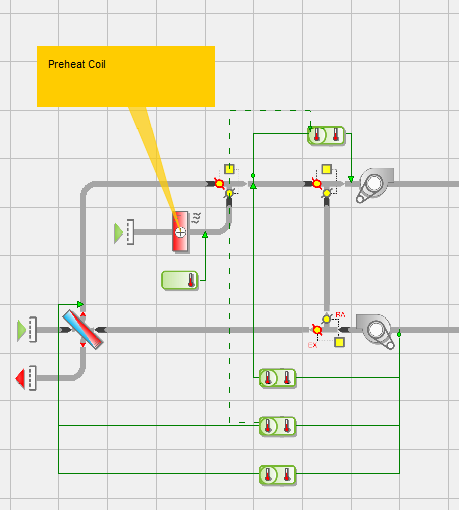
Preheat coils included in the proposed design need to be modelled as part of the baseline system. Prototype systems 7f and 8b include preheat coils as examples. This preheat coil and its controller can be copied into a baseline system in ApacheHVAC to meet this requirement of the performance rating method.
Figure 1: Preheat coil copied from Prototype System 7f into PRM Baseline System 5.
4 Demand Control Ventilation
90.1-2013 Section 6.4.3.8
Demand control ventilation (DCV) is required for all ventilation systems with design outdoor air capacities greater than 3,000 cfm serving areas larger than 500 ft2 and having an average design occupancy density exceeding 25 people per 1,000 ft2. This typically includes assembly spaces such as theaters, meeting rooms, ballrooms, etc. Systems with a design outdoor airflow less than 1200 cfm are excluded from this requirement.
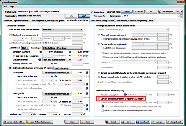
In ApacheHVAC, PRM Baseline Systems 9, 10, and 11 include pre-defined options for DCV. Users can enable DCV on these systems by checking the “Demand-controlled ventilation using zone CO2 sensors” box on the Zone Ventilation & Exhaust tab of the System Parameters dialog.
Figure 2: Zone Ventilation & Exhaust tab of the System Parameters dialog with DCV option highlighted.
For PRM Baseline Systems in ApacheHVAC that do not include the option for DCV, modellers may use Prototype System 5b as an example for adding the damper and controllers to the baseline system.
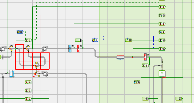 Figure 3: Prototype System 5b with network and controllers relevant to DCV selected
As an alternative to DCV (defined in Section 6.4.3.8 Exception 1), systems may be provided with air-to-air heat recovery systems complying with 90.1-2013 Section 6.5.6.1.
5 Economizers
90.1-2013 Section G3.1.2.7
Whether or not the baseline building HVAC system has an economizer depends on the type of system for the baseline building. HVAC systems 1, 2, 9, and 10 will never have an economizer; systems 3 through 8 and 11, 12 and 13 will have an economizer if the building is not located in climate zone 1A, 1B, 2A, 3A or 4A. See exceptions for gas-phase air cleaning and supermarket open refrigerated casework systems.
When an economizer is required, it must have a high-limit shutoff switch (90.1-2013 G3.1.2.8) that senses dry-bulb temperature and shuts off economizer operation (reduces outdoor air to the minimum required for ventilation) when the outdoor temperature exceeds the values show Table G3.1.2.6. The specific high-limit shutoff temperature depends on the climate zone.
In ApacheHVAC, PRM Baseline Systems 3 through 8 and 11, 12 and 13 have an economizer with the dry-bulb temperature high-limit set to 70°F by default. The high-limit temperature can be changed (or the economizer can be disabled) by accessing the System Parameters tab of the System Parameters dialog.
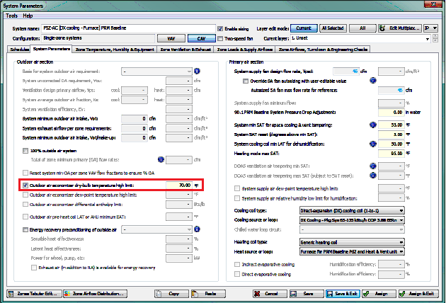 Figure 4: System Parameters tab of the System Parameters dialog with economizer option highlighted
Dry-bulb high-limit economizers may increase energy use in dry or cold climates when spaces are humidified. This does not preclude modeling the baseline system with humidification and economizer operation.
Updates have been provided in 90.1 2013 to cover systems that serve computer rooms, see section G3.1.2.7.1.
· Systems that serve computer rooms that are HVAC System 3 or 4 shall not have an economizer
· Systems that serve computer rooms that are HVAC System 11 shall include an integrated waterside economizer meeting the requirements of Section 6.5.1.2 in the baseline building design. If the simulation software cannot model an integrated water-side economizer, then an air-side economizer shall be modelled.
Manual inclusion/exclusion of economisers in the baseline mode is required by the user in this particular case
6 Exhaust Air Energy Recovery
90.1-2013 Section G3.1.2.11
The exhaust air energy recovery requirement is defined relative to climate zone, supply air flow rate, the percentage of outdoor airflow at full design airflow rate and the operational hours, per Table 6.5.6.1-1 and 6.5.6.1-2
The energy recovery system in the baseline building shall have a recovery effectiveness of at least 50%. The energy recovery system does not negate the requirement for an outdoor air economizer when economizer is required for the baseline building system. Furthermore, the baseline building system must permit air to bypass the energy recovery system during economizer operation. There are exceptions to the heat recovery requirements for specific climates, semi heated spaces with no air-conditioning, systems that exhaust toxic fumes or kitchen grease, systems serving laboratories with exhaust rates of 5,000 cfm or greater, and other conditions (see Exceptions to 6.5.6.1 in 90.1-2013).
PRM Baseline systems 3 through 11 in ApacheHVAC include the option for airside energy recovery but it is disabled by default. To engage the pre-defined energy recovery, check the “Energy recovery preconditioning of outside air” box on the System Parameters tab of the System Parameters dialog.
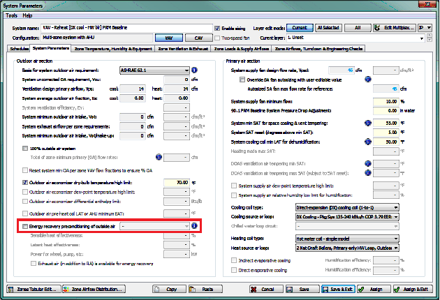 Figure 5: System Parameters tab of the System Parameters dialog with energy recovery option highlighted
7 Ventilation
90.1-2013 Section G3.1.2.6
Section G3.1.2.9 outlines the parameters around the minimum ventilation system outdoor air intake flow
A new exception has been added for 90.1 2013 and it states that for baseline systems serving only laboratory spaces that are prohibited from recirculating return air by code or accreditation standards, the baseline system shall be modeled as 100% out door air.
Where applicable, this will require a manual update to the baseline system by the user.
8 Design Airflow Rates
90.1-2013 Section G3.1.2.9
Section G3.1.2.9 outlines the parameters around the baseline building design airflow rates for all systems other than 9 and 10.
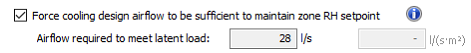
A new exception has been added for 90.1 2013 and it states that If the proposed design HVAC design airflow rate based on latent loads is greater than the design airflow rate based on sensible loads, then the same supply-air-to-room-air humidity ratio difference (gr/lb) used to calculate the proposed design airflow shall be used to calculate design airflow rates for the baseline building design.
Where applicable, this will require a manual update to the baseline system by the user. This is facilitated via a tick box in the systems parameters dialog that allows the system to size based on Relative Humidity.
9 Updates for System 11 (Computer Rooms)
90.1 2013 has added a new system, no.11 – SV-VAV, which is associated with computer rooms. In other sections of this document, references are made to this system e.g. economisers. This section is used to detail other updates in 90.1 2013 specific to this system type:
· Table G3.1.10 – If the proposed design includes computer room humidification then the computer room humidification system, schedules, and setpoints in the baseline building design shall be the same as in the proposed design
o In this case the humidification system, schedules, and setpoints from the proposed model needs to be transposed over to the baseline network by the user.
· Table G3.1.10 – For systems serving computer rooms, the baseline shall not have reheat for the purpose of dehumidification
o This has been included by default in baseline system 11
· Table G3.1.2.10 – Baseline fan brake horsepower for variable volume System 11 shall be - CFMs × 0.00062 + A
o This has been included by default in baseline system 11
· G3.1.3.17 – System 11 Supply Air Temperature and Fan Control. Fan volume shall be reset from 100% airflow at 100% cooling load to minimum airflow at 50% cooling load. Supply air temperature setpoint shall be reset from minimum supply air temperature at 50% cooling load and above to space temperature at 0% cooling load.
o The ability to modulate based on cooling load, specific to baseline computer spaces, has been provided in the 90.1 2013 navigator based on the following:
§ The cooling load demand in computer spaces (denoted by the assignment of the template ‘SPACE: Computer Room’) is dominated by the equipment load.
§ This equipment load is scheduled around a set profile for the baseline model, see section 17. This set schedule can be used to modulate the airflow and temperature controls for this specific case.
§ A new link has been provided in ApacheHVAC called ‘Modulate by Load’. When setting up a baseline system 11 serving computer spaces this link should be selected for the cooling airflow controller (MC3) and cooling temperature controller (MC1). This will then reference the necessary profiles to help achieve the above requirement. Note that the airflow control is based on a minimum airflow of 30%.
10 Equipment Efficiencies
90.1-2013 Section G3.1.2.1
The minimum efficiencies for HVAC equipment (6.4.1) must be used for the applicable equipment in the baseline building design. This includes any part load efficiencies if these are specified. Minimum HVAC equipment efficiencies are defined in sections 6.4.1.1, 6.4.1.2, 6.4.1.3, and 6.4.1.4 of 90.1-2013. Note that Chillers shall use Path A efficiencies as shown in Table 6.8.1-3
The pre-defined DX Cooling types provided in ApacheHVAC are set up to meet 90.1 PRM requirements for Baseline systems. There are 11 pre-defined systems available:
· 5 for Packaged Single-Zone (PSZ) systems for different size ranges and associated COPs
· 3 for Packaged Terminal Air-Conditioning (PTAC) for different size ranges and associated COPs
· 3 for Packaged Terminal Heat Pumps (PTHP) for different size ranges and associate COPs
The COP values in the pre-defined DX Cooling types are adjusted per section G3.1.2.1 to remove supply fan power.
The DX Cooling Type dialog provides the EER with supply air fan from 90.1 Chapter 6 tables only in the reference name of the DX Cooling Type. The actual number used in the input field for that dialog is the COP without the fan, i.e., after applying the new method detailed in G3.1.2.1 for removing the supply fan power.
11 Hot Water Supply Temperature Reset
90.1-2013 Section G3.1.3.4
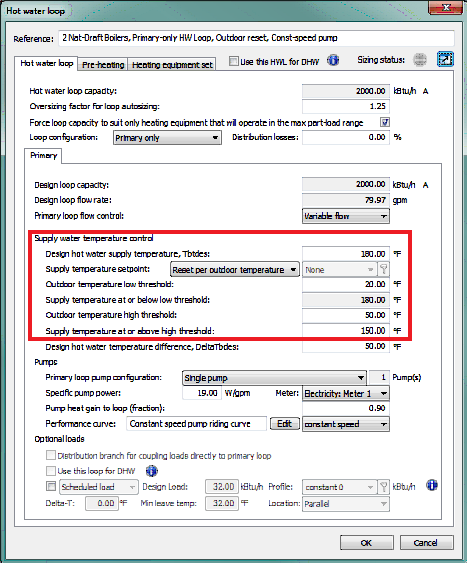
For baseline building systems 1, 5, and 7, 11 and 12 the hot water supply temperature shall be reset based on the outdoor dry-bulb temperature. When the outdoor temperature is 20°F and below, the supply temperature shall be a constant 180°F. When the outdoor temperature is 50°F and above, the supply temperature shall be 150°F. When the outdoor temperature is between 20°F and 50°F, the supply temperature shall be ramped in a proportional manner between 180°F and 150°F.
In ApacheHVAC, the PRM Baseline Systems 1, 5, and 7, 11 and 12 include this hot water supply temperature reset by default.
Figure 6: Default hot water loop supply water temperature control settings for a PRM Baseline System 5
12 Hot Water Pumps
90.1-2013 Section G3.1.3.5
The baseline building design hot water pump power shall be 19 W/gpm (except for purchased hot water or steam). The hot water loop shall be modelled as primary-only with continuous variable flow. Systems serving 120,000 ft2 or more shall be modelled with variable speed drives, otherwise, the systems shall be modelled as riding the pump curve.
Default hot water loops for PRM Baseline Systems in ApacheHVAC are primary-only variable flow, have a specific pump power of 19 W/gpm, and use a constant speed pump curve. When the area of the building served by the hot water loop exceeds 120,000 ft2, users will need to change the pump performance curve to variable speed using the pull-down menu in the Hot water loop dialog.
Figure 7: Default hot water loop pump configuration for a PRM Baseline System 5
In 90.1-2013, an exception to G3.1.3.5 states that pump power shall be 14 W/gpm for systems using purchased heat. Users will need to adjust the Specific pump power in ApacheHVAC accordingly.
13 Chiller Selection
90.1-2013 Section G3.1.3.7
For baseline system types 7, 8, 11, 12 and 13, the number and type of electric water-cooled chillers to be modelled is determined as a function of building peak cooling load. When the building peak cooling load is less than or equal to 300 tons, a single screw chiller is required. When the building peak cooling load exceeds 300 tons but is not larger than 600 tons, two equally sized screw chillers are to be used.
For models where the baseline building peak cooling load exceeds 600 tons, a minimum of 2 equally sized centrifugal chillers must be used. No chiller, however, can be greater than 800 tons so the addition of more equally sized chillers may be required on large projects.
PRM Baseline Systems 7, 8, 11, 12 and 13 in ApacheHVAC include a single water-cooled centrifugal chiller by default. For baseline buildings where the peak cooling load does not exceed 300 tons, no additional chillers are needed, but the chiller curve selection will need to be updated to a screw-type chiller.
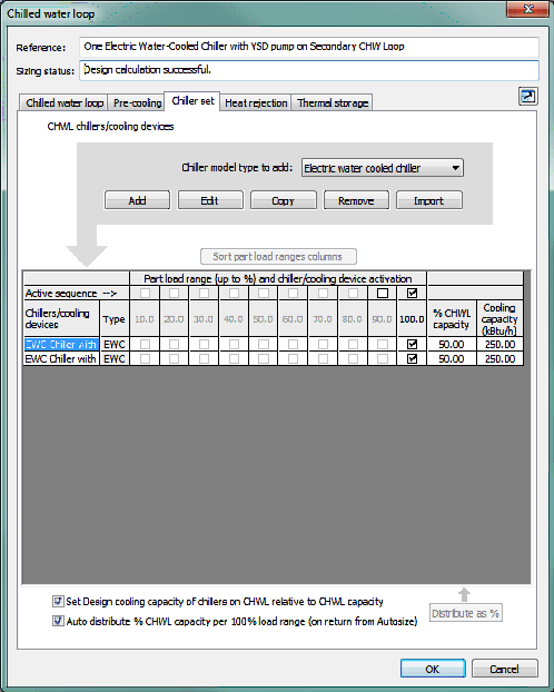
If the peak cooling load in the baseline building exceeds 300 tons but is not larger than 600 tons, users can add a second chiller to the chilled water loop by using the Copy button on the Chiller set tab of the Chilled water loop dialog. Both chillers will need screw curve sets (not the default centrifugal curves) so it is recommended that this change be made prior to using the Copy button. Users should ensure that the chillers are equally sized and can do so quickly by setting the % CHWL capacity to 50% for each chiller.
Figure 8: Chiller set tab of the Chilled water loop dialog illustrating two equally sized chillers for a PRM Baseline System 7 serving a peak building cooling load of 500 tons
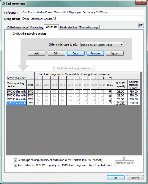
If the peak cooling load in the baseline building exceeds 600 tons, users can copy the default chiller until there are enough chillers on the chilled water loop to satisfy the building peak cooling load without any chiller exceeding 800 tons in size. Every loop must have at least 2 chillers and all chillers must be equally sized.
For example, a model where the baseline building peak cooling load is 700 tons requires 2 x 350 ton chillers. Where the baseline building peak cooling load is 3,000 tons, the model requires 4 x 750 ton chillers.
Figure 9: Chiller set tab of the Chilled water loop dialog illustrating four equally sized chillers for a PRM Baseline System 7 serving a peak building cooling load of 3,000 tons
It should be noted that the default baseline chiller curves come from the generic curve sets in DOE-2.2 and are based on entering condenser temperature (ECT). The manufacturer-specific curves available to users in the Performance Curve library are based on leaving condenser temperature (LCT). If LCT curves are used for proposed chillers, users may consider following the steps below to better isolate the results of actual differences in the baseline and proposed chiller plants (e.g., differences in chiller COP, design sizing, supply water temperature set points, etc.):
· Define appropriate curve set for proposed chiller & test via simulation to confirm that the chiller is modeling as expected.
· Save a copy of that chiller with a new name for the Baseline chiller.
· Revise the COP at the rated condition to match the ASHRAE 90.1 requirements for minimum chiller performance in Chapter 6.
· Confirm that the IPLV is at least that required for 90.1. Data needed for IPLV calculations can be found by reading the values at the four required load ranges from the 2D plots in the ApacheHVAC Performance Curves Library interface. Derivation of IPLV for each chiller curve set will be included in a future release of the VE.
In 90.1-2013, an exception to G3.1.3.7 states that systems using purchased chilled water shall be modelled using different guidelines as defined in G3.1.1.3. If you have questions about modifying the PRM Baseline Systems in ApacheHVAC to meet these requirements, please contact support@iesve.com.
14 Chilled Water Supply Temperature Reset
90.1-2013 Section G3.1.3.9
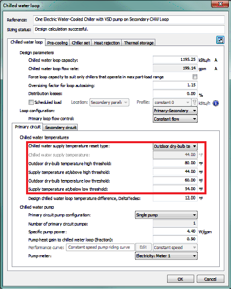
For baseline building systems 7, 8, 11, 12 and 13 the chilled water temperature shall be reset on an hourly basis, based on the outdoor air temperature. When the outdoor temperature is 80°F or greater, the supply temperature shall be a constant 44°F. When the outdoor temperature is 60°F or below, the supply temperature shall be 54°F. When the outdoor temperature is between 60°F and 80°F, the supply temperature shall ramp between 44°F and 54°F in a proportional manner. If there is dehumidification requirement of the cooling coils, the maximum reset of chilled water temperature should be calculated according to the dehumidification requirement and cooling coils performance.
In ApacheHVAC, the PRM Baseline Systems 7, 8, 11 12 and 13 include this chilled water supply temperature reset by default.
Figure 10: Default chilled water loop supply water temperature control settings for a PRM Baseline System 7
In 90.1-2013, an exception to G3.1.3.9 states that if the baseline chilled-water system serves a computer room HVAC system, the supply chilled-water temperature shall be reset higher based on the HVAC system requiring the most cooling; i.e., the chilled-water setpoint is reset higher until one cooling-coil valve is nearly wide open. The maximum reset chilled-water supply temperature shall be 54°F.
In order to meet this requirement a manual update would be required by the user to set the reset method to ‘CHW Loop Load’ when computer rooms are included.
15 Chilled Water Pumps
90.1-2013 Section G3.1.3.10
For baseline building systems 7, 8 and 11, pump power shall be 22 W/gpm. Chilled water pumps in systems with a cooling capacity of 300 tons or more shall be modelled as primary/secondary systems with variable speed drives on the secondary pumping loop. Chilled water pumps in systems with less than 300 tons cooling capacity shall be modelled as primary/secondary systems with the secondary pump riding the pump curve.
Default chilled water loops for PRM Baseline Systems in ApacheHVAC are primary/secondary configuration with constant flow on the primary loop. The primary loop has a specific pump power of 4.4 W/gpm with the pump riding the pump curve and the secondary loop has a specific pump power of 17.6 W/gpm with a variable speed curve. When the cooling capacity of the baseline building is less than 300 tons, users will need to change the pump performance curve on the secondary loop to constant speed using the pull-down menu in the Chilled water loop dialog.
In 90.1 2013 a specific requirement is included for computer rooms and states that for computer room systems using System 11 with an integrated water-side economizer, the baseline building design primary chilled-water pump power shall be increased 5 W/gpm for flow associated with the waterside economizer. This is a manual update required by the user if an integrated waterside economizer (rather than an airside economiser) is chosen for this particular case.
Also in 90.1-2013, an exception to G3.1.3.10 states that pump power shall be 16 W/gpm for systems using purchased chilled water. Users will need to adjust the Specific pump power in ApacheHVAC accordingly.
16 Heat Rejection
90.1-2013 Section G3.1.3.11
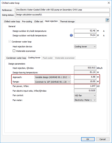
For baseline building systems 7, 8, 9, 12 and 13 the heat rejection device shall be an axial fan cooling tower with variable speed fans. Baseline cooling tower power should be calculated using Table 6.8.1-7. In ApacheHVAC, PRM baseline systems 7, 8, 12 and 13 have a cooling tower with a variable speed fan by default. The fan power is calculated based on heat rejection load and the default fan electric input ratio. Users should edit the cooling tower fan power to meet the requirements of Table 6.8.1-7.
Section G3.1.3.11 goes on to state that the condenser water design supply temperature shall be calculated using the cooling tower approach to the 0.4% evaporation design wet-bulb temperature as generated by the formula below with a design temperature rise of 10°F.
Where WB is the 0.4% evaporation design wet-bulb temperature in °F; valid for wet bulbs from 55°F to 90°F.
This new functionality has been provided to the necessary 90.1 2013 baseline systems when accessed from the 90.1 2013 navigator.
Within the default chilled water loop dialog a new set of options have been provided in the Heat Rejection > Cooling Tower tab for Approach and Range settings.
Note that these are the default settings for the relevant baseline systems.
The standard requires the baseline building design condenser water pump power to be 19 W/gpm. This is the default specific pump power in ApacheHVAC for PRM baseline systems 7, 8, 12 and 13.
For computer rooms using System 11 with an integrated water-side economizer, the baseline building design condenser water-pump power shall be increased 5 W/gpm for flow associated with the water-side economizer. This is a manual update required by the user if an integrated waterside economizer (rather than an airside economizer) is chosen for this particular case.
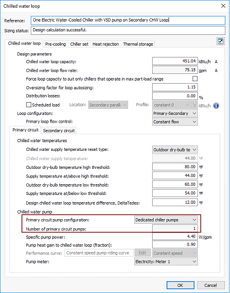
The standard also requires that each chiller shall be modelled with separate condenser water and chilled water pumps interlocked to operate with the associated chiller. By default, ApacheHVAC includes a single chilled water pump and single condenser water pump. Users should change this setting when multiple chillers exist. This can be done by changing the Primary circuit pump configuration pull-down menu on the Primary circuit sub-tab of the Chilled water loop tab and the Condenser loop pump configuration on the Condenser water loop sub-tab of the Heat rejection tab.
Figure 11: Chilled water loop tab with dedicated pumps selected on the chilled water loop for a PRM Baseline System
17 Computer Room Equipment Schedules
90.1-2013 – Section G3.1.3.16
Section G3.1.3.16 states that, in the baseline model, the computer room equipment schedules shall be modelled as a constant fraction of the peak design load per the following monthly schedule:
· Month 1, 5, 9—25%
· Month 2, 6, 10—50%
· Month 3, 7, 11—75%
· Month 4, 8, 12—100%
The software has been updated to assign an equipment modulating profile to all computer rooms within the baseline model that follows the schedule outlined above.
The profile is called 'BLDG: Data Center - Equip' (annual profile) and is assigned to the baseline model computer spaces during creation of the baseline model (generate baseline action item).
Computer rooms are identified as those assigned to the ‘SPACE: Computer Room’ thermal template using the space by space method room grouping scheme.
18 Dehumidification
90.1-2013 – Section G3.1.3.18
Section G3.1.3.18 discusses dehumidification for Systems 3 through 8 and states that If the proposed design HVAC system(s) have humidistatic controls, then the baseline building design shall use mechanical cooling for dehumidification and shall have reheat available to avoid overcooling.
These baseline systems have dehumidification controls built in.
Section G3.1.3.18 goes on to state that when the baseline building design HVAC system does not comply with any of the exceptions in Section 6.5.2.3, then only 25% of the system reheat energy shall be included in the baseline building performance. The reheat type shall be the same as the system heating type.
As most system will not comply with the exceptions to section 6.5.2.3 this requirement has been built into the reporting for 90.1 2013 by default. However, this can be overwritten by the user via a tick box at the top of table 1.8.1 in the BPRM report.