Appendix H: Modeling UFAD and DV in ApacheHVAC
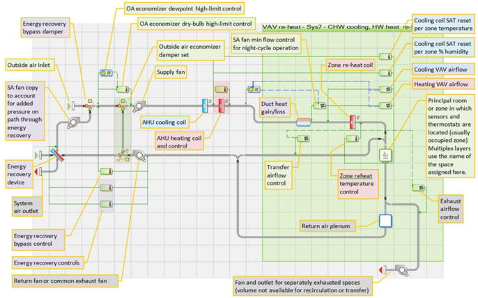
The HVAC systems library includes two pre-defined UFAD system prototypes. One is intended for more humid climates for which dehumidification will be required, and thus includes an optional heat pipe/wheel/runaround coil in the AHU. The other simply excludes this feature. The labeled image of the prototype UFAD system below is as it appears in version 6.5 (VE 2012).
· There’s little value in modeling UFAD without stratified thermal zones, as this is the primary means of obtaining energy savings with such systems, so treat this as a given in the proposed model. Including the UFAD plenum geometry is also important for understanding actual supply temperatures after gain in the plenum.
· It is essential, especially in larger models, to ensure that loads in the stratifies zone normally specified in terms of W/ft2 (or m2) are entered and converted via the Space Data Tabular Edit view to absolute values (btu/h or W) before replacing the “floor” surface of the stratified zone with a “hole” to the occupied zone below. Changing the input mode for all stratified zones in the building can be done simultaneously via a single selection change of this parameter in Space Data Tabular Edit view with all stratified zones selected and ticked in that view.
· How to split loads depends upon building type/use. For offices and similar spaces, it is generally advisable to place loads as follows:
o Lighting gains: 100% in the stratified zone if pendant or surface-mount fixtures; split between stratified zone and the RA plenum zone if the fixtures are flush mounted in a drop ceiling that defines a return plenum. The surfaces in occupied zone below will, along with those in the stratified zone, “see” the radiant fraction of the lighting gain. Set the radiant fraction according to the general type of light fixtures or data for actual fixtures.
o Occupants gains: 100% in the occupied zone, as this simplifies ventilation calculations and introduces some conservatism with respect to not relying upon thermal plumes from occupants that may be moving about enough to re-mix the stratification as much as they add to it. (Note: If the space is a theater or similar with stationery occupants being the dominant load, however, it then makes sense to split the occupant load partly to the stratified zone.)
o Equipment gains: Split these gains between occupied and stratified zones according to anticipated distribution of actual convective gains. Determine the split via CFD studies for the project, physical measurements in a mock-up, research literature, or other means appropriate to the project scale, scope, resources, and level of detail required.
As a default until better data can be obtained, and assuming the occupant gain is placed 100% in the occupied zone, an even 50/50% split between the occupied and stratified zones is a reasonable starting point for most UFAD systems, and a 30/70% split between occupied and stratified zones is a reasonable starting point for true thermal displacement ventilation (DV) systems that gently “pour” a pool of cool air onto the floor (i.e., not using swirl diffusers).
· The pre-defined UFAD systems in ApacheHVAC include a “re-mixing” path and control for use in zones that include a fan-powered box for heating (typically perimeter zones). This feature partially mixes the space, reducing thermal stratification consistent with the flow rate from each particular zone fan-powered box. It does so in a particular zone only when its fan runs. It is important to understand how your particular system is designed, as this remixing behavior will not be present for all applications.
· In the case of the ASHRAE 90.1 PRM for LEED and similar performance rating systems, the re-mixing path and control can also be used in a baseline (non-stratified) version of the same system to destroy the stratification at all times and to more completely mix the space, rather than partially mixing the space consistent with the flow rate from a particular fan-powered box only when heating is engaged.
· When autosizing a UFAD system and corresponding baseline VAV system for comparison, as is typical, it is important to make some adjustments to the autosizing process to calculate the correct zone-level airflow rates for both the proposed and baseline models. There is one simple customization of the Loads Data spreadsheet that needs to be made for each of these two system models, as follows.
1. UFAD System: Adjust the supply temperatures in the Room Design Airflows tab of the Loads Data spreadsheet for the Proposed UFAD HVAC system so that heat gain in the UFAD plenum will be accounted in the airflow calculation. In other words, the airflow calc needs to account for both the loads in the occupied zone and the load picked up by the supply air in the UFAD plenum. This is represented as an adjusted supply air temperature, and therefore a reduced delta-T, which will increase the design supply flow rate accordingly. The following example shows this adjustment as made by inserting a new column for UFAD supply plenum heat gain within the Room Design Airflows tab of the Loads Data spreadsheet for the UFAD system. The values for gain in degrees°F in the new column are simply added to the supply air temperature normally reported in the next column.
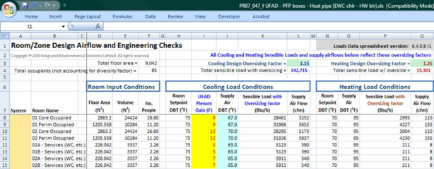
The plenum gain numbers can be set to typical values to begin with (e.g., 2–5 °F), and then later adjusted according to results of an initial system-level sizing run.
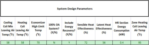
This adjustment of the supply air temperature for UFAD airflow should be done independent of the SAT and reset values for the AHU cooling coil entered in the System Parameters dialog. This dialog edits the system tabs of the corresponding Loads Data spreadsheet, and these values set the LAT at the AHU cooling coil, which will differ from the SAT at the diffusers. Because the coil LAT must be lower to address the heat gain in the UFAD plenum, and may need to be colder still for dehumidification, the AHU input parameters must be set independent of the zone SAT that is used for airflow calculations. Therefore, use the System Parameters dialog or direct editing of system design parameters on the relevant system tab, as shown below, to set the leaving temperatures for the AHU coils. Use the added column described above to adjust the SAT values for design airflow calculations.
The graph of HVAC node results for the sample UFAD model design sizing run below shows what you should look for upon completion of the system-level design sizing run (system-level design sizing for cooling will be the .cln results file, and in this case in Brisbane Australia January is the hottest month). Any simulation of the few hottest days year can be used for this test. The graph shows the significant difference between the SAT from the AHU at node 79 (dark blue line) and at the UFAD diffusers (node 59, light blue). The example spreadsheet above reflects the differences between the SAT at the AHU and diffusers for specific zones. These gains are somewhat greater than typical, given the hot sunny climate, significant direct-beam solar gain striking the raised floor top surface of the UFAD plenum, and the nature of the two-story test model (described in subsequent pages); however, not unrealistic.
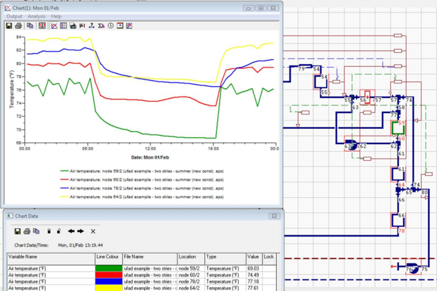
The graph below is for the second system-level design sizing run—i.e., after adjusting the plenum gain values in the spreadsheet and re-applying the resulting zone airflow values to the controllers in the HVAC system. Node 60 (green) is the occupied zone temperature, which is the essential determinant of whether or not the airflow is adequately sized to address the zone loads with the actual supply temperature exiting the diffusers. Node 64 (red) is the stratified zone and node 78 (pink) is the RA plenum. It’s worth noting that the temperature in the first-floor RA plenum is actually lower than the temperature of the first-floor stratified zone, as the RA plenum air is being actively cooled by the second-floor UFAD supply plenum sitting on top of the metal and concrete floor deck that separates these two plenums.

2. Baseline system: Use either the same system model running the remixing path at all times or a dedicated system model, such as a standard VAV system, with the stratified zone and remixing path added. Thus the baseline system or any alternative version of the proposed that is not meant to be stratified can be modeled without removing the partitioning for thermal stratification from the thermal zones in the model. The multiplex region within the Baseline VAV system will exclude the UFAD supply plenum but will include the stratified zones in series with the occupied zones, with the re-mixing path “stirring” these back together as a single “well-mixed” zone. You must do two things:
a. Either, add the stratified zone, remixing path, and controller for this from the UFAD network to the Baseline or non-stratified alternate version, as shown below, or, to run the UFAD system model as a fully-mixed system for comparison, remove the AND connection from the controller on the re-mixing path in the UFAD version so it will run continuously during the simulation.
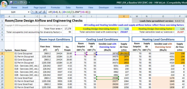
b. Zone-level loads for the occupied and stratified zones need to be combined for the autosizing of airflow controllers by adding a cell reference for this within the Loads Data spreadsheet for the system. This must be done for each Baseline or alternate non-stratified system in order to have the zone airflows properly sized to address the entire load with the space fully mixed.
This is actually quite simple. The example below shows the Loads Data spreadsheet for the Baseline VAV system in a model where the stratified zones where present at the time of zone-level autosizing. The formula in cells K8 through K11 have been modified to add the loads from cells J16 to 19, respectively. This will then size the design cooling airflow to the occupied zones according to the total load in occupied plus stratified zones. The same is done for the heating loads and airflow calculations. The controller airflow settings need to be updated (Assign System Parameters and Room Sizing Data in the workflow navigator) after combining the loads in the spreadsheet airflow calculation.
To get the stratified zones to show up in the spreadsheet in a list following the corresponding occupied zones, the stratified zones must first be organized in the model browser (normally by name) so that the sorted list of stratified zones will be exactly parallel to the corresponding occupied zones (same number of zone sin the exact same order). The stratified zones should be assigned to a group that matches the room group used to assign occupied zones to a particular AHU. Having done so, you must temporarily assign the appropriate group of stratified zones to the same ApacheHVAC system multiplex as the corresponding set of occupied zones (i.e., on additional rows below the occupied zones within the same multiplex edit dialog). Be sure not to rep[lace or delete multiplex rows for any occupied zones. Then run the zone-level sizing, which will generate a spreadsheet as shown above with the stratified zones listed below the occupied zones. If you already have baseline system spreadsheets that you want to keep, move them for the time being to a folder with a new (custom) name before running the zone-level sizing so that this will generate a new spreadsheet for each system. Then modify formula in the spreadsheet columns K and P on the Room Design Airflows tab so that the loads from occupied and stratified zones are added in these columns as described above. Once you have done all this, you will need to delete the added (stratified zone) layers from the HVAC system multiplex(es); however, be sure to leave the added rows in the spreadsheet. Thus, once having assigned to spreadsheet values to controls in ApacheHVAC, the airflow controllers on each occupied zone multiplex layer will have flow rates based upon the combined load, including the corresponding stratified zone for each.
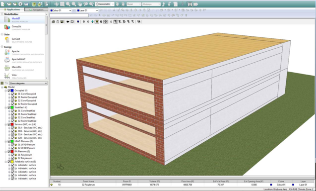
The image below illustrates an appropriate test model for a very large building with numerous identical spaces served by a UFAD system. The divisions on the side of the model show occupied and stratified core and perimeter zones, common UFAD and RA plenums, and non-UFAD services zones at the back of the core zone. Apart from the one exterior façade, this small piece of the larger building is surrounded on all sides other zones. Whether they exist in the model or are represented by simplified dummy zones, these adjacent spaces are placed on a separate layer in ModelIt, and this layer is de-activated (status = off) in the Layer Properties dialog, thus making all the adjacencies effectively adiabatic (the thermal mass of the constructions is still present, but the net heat transfer across any adjacency is zero) without exposure to outdoor conditions. This allows much faster testing and experimentation for these representative zones.
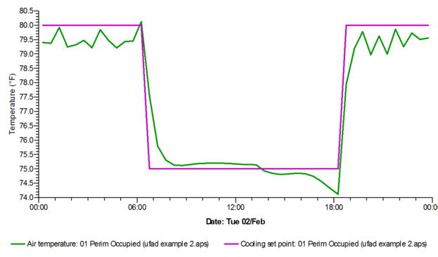
The following are examples of the sort of results from a single hot day in an initial simulation run that should be checked to ensure that loads are being met and thermal stratification is being modeled as intended. This also illustrates how the modeling results can be used to explore and communicate the thermal effects associated with the assumed plume factors for internal gains.
Similar results can also be queried for nodes in the HVAC system to confirm system operation and to analyze the influence of both primary SA duct and UFAD plenum gains.
· As for whether or not to include the UFAD plenum in the model, there are a number of advantages in terms of modeling how UFAD systems actually work. It is valuable and perhaps essential to explicitly model the UFAD supply plenum whenever one or more of the following is true:
c. The raised floor top surface of the UFAD plenum sees direct-beam solar gain.
d. The UFAD plenum is sitting on a floor deck that has a warm return plenum below it, as in many multi-story projects.
In either of these two cases, there will be significant gain to the plenum, and thus the supply air temperature to the zone will not be the same as the leaving temperature from the AHU (regardless of whether you’re including duct heat gain). As the plenum area is generally large, gain to the plenum can be substantial. A study by the UC Berkeley Center for the Built Environment (CBE) showed that, even for a core zone, as much as 40% of cooling load for a typical multi-story office space with RA plenum below the floor deck can accrue to the supply air in the UFAD plenum before it reaches the diffusers. When direct beam solar is striking the raised floor, heat gain in the UFAD supply plenum can be much greater.
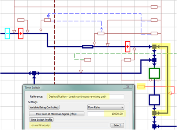
· Apart from its use as described above for re-mixing the occupied and stratified zones to model a non-stratified system for comparison, the re-mixing path and control is used to de-stratify the model in spaces that are served by a UFAD system and have a fan-powered box for reheat (such as perimeter zones or private offices), and where this fan-powered box is able to stir the space. This might extract room air as an induced secondary airflow into the fan-powered box (how the ApacheHVAC prototype UFAD system is set up by default) or simply couple the fan-powered box to a diffuser that blows air up the glazed perimeter wall. In any case, if the UFAD system is design and implemented properly, there will be good stratification in cooling mode and little to no stratification in heating mode. This captures the benefits of thermal stratification for cooling mode and avoids wasting that warm air when the occupants need it. The modeling of this is intended to de-stratify the space when and only when the fan-powered box is operating, and this is the reason for the logical AND connection from the remixing controller to the airflow control on the fan-power-box secondary/re-circulated airflow path.
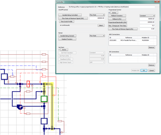
The remixing path is highlighted in yellow below. The controller for this is in red, including the logical AND connection to the fan-powered box controller, and the controller dialog is at right. The controller uses a simple proportional relationship to ramp up the re-mixing flow directly in proportion to the flow from the UFAD diffusers to the occupied zone.
· Distribution of radiant exchange in thermally spaces modeled as an occupied plus stratified zone:
The radiant fraction of an internal gain is seen by all “surfaces” in the space to which the gain is assigned. The term “surfaces” is in quotes here, as this includes the hole that connects the occupied and stratified zones in each room. As such, if, for example, the ceiling above and hole at the base of the stratified zone in a particular room were to account for 80% of the total “surface” area of that stratified zone, then 40% of the radiative energy would initially strike the ceiling and 40% would strike the hole as a “surface”. The remaining 20% would be distributed among the walls of the stratified zone in proportion to their surface area. In other words, as a proxy for actual view factors, which can get very computationally weighty, the radiant energy is distributed to surfaces as an area-weighted proportion of the total.
Once the radiative energy from the internal gain has been distributed, along with other radiative inputs, surface temperatures and the differences thereof are used to calculate radiant exchange between surfaces. When the hole as a pseudo “surface” between occupied and stratified zones receives radiation from the lights, it has no capacity to store thermal energy, and thus does not heat up and convectively heat the adjacent air as normal surfaces would; however, it does immediately communicate the radiation it receives to all of the surfaces that it can “see”. This re-distribution is done in proportion to surface area and temperature of receiving surfaces, as with other radiant exchanges. As such, the hole acts somewhat like a diffusing lens that scatters the radiation passing through it according the area and relative temperature of the surfaces it can see.
· Because the hole connecting the occupied and stratified zones has no surface area as a “floor” for that space in the 3D model, if the lighting gain in the stratified is to set in terms of W/m^2, this needs to be done prior to creating the 100% hole in the partition separating the occupied and stratified zones. Once these gains have been specified in W/m^2, select all stratified zones and use the Tabular Space Data tool in the Apache Thermal view with all rows selected in that window to simultaneously change the Input Mode for all lighting gains in the stratified zones from W/m^2 to W. You’ll need to do the same for the stratified fraction of equipment and task-light loads (see below) prior to adding the holes between zones, otherwise these gains will be set to zero when you replace the “floor” partition for the stratified zone with a hole of the same area.
· If you have a return plenum at the ceiling AND the light fixtures are mounted within the drop ceiling such that a fraction of the radiant and convective go directly to the RA plenum, defined a separate lighting gain for the plenum. If, for example, you had 10 W/m^2 total lighting gain with 20% overall going to the plenum and 40% overall radiative, you would have two lighting gains defined: Stratified zone = 8 W/m^2 and 40% radiative and Plenum zone = 2 W/m^2 and 40% radiative. This assumes that the top surface of the fixture is white painted metal or plastic, etc., such that is has typical emissivity and thus the portion of gain directed up into the plenum as radiant energy will be similar to that directed down into the room.
· For a UFAD system (as with DV or radiant cooling) including the radiant fractions for these gains is important, as the top and bottom constructions (raised floor and floor deck below) will be cooled by the supply air—much like a radiant cooling slab. The same is true for DV systems that gently “pour” cool air to form a more or less continuous shallow pool of cool air on the floor. The floor gets cool. As the raised floor of a UFAD plenum is cooler than the ceiling it can see above, which is surrounded by the stratified zone and RA plenum, it will received radiant heat from the ceiling. As long as there is thermal stratification, this will be true for the model and in the real world. Similarly, in a multi-story building, because the floor deck under the UFAD plenum will be cooled by the supply air—like an air-cooled version of a hydronic radiant slab—it will receive both radiative and convective gain from the much warmer RA plenum below. The result of gain at the top and bottom of the UFAD plenum is gain in the supply air, just as in the real-world plenum. Even when there is no direct-beam sun striking the raised floor surface, gain to the supply air in the plenum can account for as much as about 14% of the gain removed from the space. When there is direct-beam solar striking the raised floor, this can be much greater.
· In keeping with the logic above for lighting in a commercial office space, gains for both equipment/task lights and people will need to be appropriately distributed. Because equipment and task lights tend to be stationary, these will have stronger and more consistent thermal plumes. Therefore, depending upon the mix of actual devices, the plume factor for these might be on the order of 70%—i.e., 70% of their gain should be directly assigned to the stratified zone. As for radiant fraction, however, only the portion of the gain assigned to the occupied zone (the actual location of the equipment
· As noted above, if equipment/task-light gains are to be specified in W/m^2, the fraction of the gain that will be assigned to the stratified zone needs to be placed there and converted to an absolute gain (expressed in Watts) prior to replacing the partition surface with a hole.
· As people are much less consistent with respect to thermal plumes (they tend to fidget, move about, and sometime breath with some force, thus making for inconsistent thermal plumes), the above approach to lighting, equipment, and task lights will account for much of the dependable thermal stratification from internal gains. What to do with the occupant gains then becomes a bit of a judgment call with respect to providing a fair approximation of real-world thermodynamics for the particular type of space, use, and occupancy. If the space is relatively lightly occupied, as with mainly office spaces, simply placing all occupant gains in the occupied zone introduces a modest conservatism, but simplifies inputs for occupant gains as well as occupancy-based ventilation calculations and inputs. The contribution of CO2 from occupants, which is calculated in proportion to combined sensible and latent gains for the occupants in a space at any given simulation time step, will also accrue 100% to the occupied space when all people gains are placed there. On the other hand, if the space is densely occupied and occupants will be mainly sedentary, it may be worth splitting the loads such that 30–60% of occupant gains are assigned to the stratified zone, along with lighting and/or equipment. This may be particularly important for a theater or similar space conditioned by a thermal displacement ventilation (DV) system.
· If a separate people gain is used to assign a portion of heat from occupants to the stratified zone, the split between the occupied zone and stratified zone gains should be done as follows: Let’s use the example of a relatively densely occupied call center with each occupant given 4 m^2 of space (about 40 sf/person). Let’s assume that, given available research or CFD modeling, it was judged that an average of 50% of the sensible thermal gains from occupants would accrue to the stratified zone in the form of thermal plumes, thus bypassing the occupied air volume and thermostat. Let’s also assume that, given the slightly tense and stressful nature of the call center work, the sensible gain per occupant was estimated to average 120 W/person and the 75 W/person latent gain will be omitted from consideration with respect to thermal plumes (although this is a bit of a simplification, all latent gain will be assumed to be mixed with the occupied air volume by occupant breathing and movement, rather than some of it being transferred immediately to the stratified zone).
· Begin, before replacing the partition between occupied and stratified zones with a hole, by creating separate people gains for the occupied and stratified zones. Both should use the full occupant density of 4 m^2 per person, which will aid in other occupant-dependent inputs and calculations for the occupied zone; however, both will use only 50% of the sensible gain (60 W/person for each). While full 75 W/person latent gain will be used for the occupied zone people gain, the latent gain will be set to zero W/person for the stratified zone (the latent gain, as with CO2 added to the occupied zone, will eventually pass through the stratified zone, but only after being fully mixed with the occupied zone air and then diluted and displaced by introduction of supply air).
· Where the space is densely occupied and de-humidification will be controlled according to the relative humidity in the occupied zone, it will be important to also split the latent gains so that they accrue to both occupied and stratified zones. In the example above, it may be appropriate to include roughly 40 W/person latent gain in the occupied zone people gain and 35 W/person latent gain in the stratified zone people gain.
· Where CO2-based demand-controlled ventilation controls are to be modeled to reflect CO2 sensors that will actually be placed in the occupied zone of the built spaces, it will be important to maintain the “people” gain type in the stratified zone in order to have CO2 accrue to both occupied and stratified zones in proportion to the combined.
· Note that whenever the “people” gain type is used for internal gains directly assigned to the stratified zone, care should be taken to zero out any occupancy-based calculation of fresh air for stratified zones. The fresh air should be calculated for and introduced into only the occupied zones. The proper calculation of fresh air ventilation rates for the occupied zone is the primary reason for placing the full occupant density (number of occupants) in both occupied and corresponding stratified zones, and then adjusting the sensible and latent gains per person to reflect the thermal plume factors—i.e., reducing each to split the gains appropriately.