ApacheHVAC Interface Overview
Figure 1 - 8 : The ApacheHVAC view or module within the IES Virtual Environment.
The ApacheHVAC view comprises the interface features described below.
Virtual Environment Menu Bar

…

These menus provide functions used throughout the Virtual environment. Please refer to the
Virtual Environment User Guide for further information.
ApacheHVAC Menu Bar
These pull-down menus provide functions specific to the ApacheHVAC view.
ApacheHVAC Toolbars
The toolbars provide quick access to menu functions, selection of components and controllers to be placed on the system schematic, creation and editing of system of multiplexes, and access to system prototypes.
· New
· Open
· Save
|
· Hot water loops
|
· Direct-acting heater/cooler types
|
|
· Generic heat sources
|
· Heating coil
|
|
· Air-to-air heat pump types
|
· Cooling coil
|
|
· Heat transfer loops
|
· Air-to-air heat / enthalpy exchanger
|
|
· Water-to-air heat pump types
|
· Steam humidifier
|
|
· Chilled water loops
|
· Spray chamber / evaporative cooler
|
|
· Generic cooling sources
|
· Fan – left intake
|
|
· Dedicated waterside economizer types
|
· Fan – right intake
|
|
· DX Cooling types
|
· Mixing damper set
|
|
· Unitary cooling system types
|
· Return air damper set
|
|
· Radiator / radiant panel types
|
· Duct heat gain / loss – horizontal
|
|
· Chilled ceiling /radiant panel types
|
· Duct heat gain / loss – vertical
|
|
· Import HVAC networks from libraries, etc.
|
· Export HVAC networks (entire, subset, plant, etc.)
|
|
· Create multiplex
|
· Layers selected of layers in multiplex
|
|
· Edit multiplex
|
· Current multiplex display layer
|
|
· Local / global edit mode
|
· Layer up / down
|
|
· Room or thermal zone component
|
· Junction / flow splitters (four)
|
|
· Air inlet
|
· Straight connectors (two)
|
|
· Air outlet
|
· Elbow connectors (four)
|
|
· Network drawing tool
|
· Crossover connector
|
|
· Independent time switch controller
|
· Dependent time switch controller
|
· AND connection
|
|
· Independent controller with sensor
|
· Dependent controller with sensor
|
· OR connection
|
|
· Independent differential controller
|
· Dependent differential controller
|
|
· System schedules and setpoints
· System parameters
· Zones tabular edit view
· Global system parameter assign
· Room and zone-level sizing
· System equipment and plant sizing
· System loads, sizing, and ventilation reports
· Move
· Copy
· Query item
· Check network
· Assign zones
· Apache profiles
· Delete
· Enable/disable component tooltips
· Show/hide link for all overlays
· Show/hide overlays
· Remove all overlays
· Preferences
· Add new loop
· Edit selected loop
· Copy selected loop
· Remove selected loop
· Open loop list dialog
The last ten of the toolbar buttons above will be available along with the graphic waerside interface in ApacheHVAC and detailed component-level results in Vista-Pro as of VE 2012 Feature Pack 2.
View Toolbar
This provides functions for manipulating the view of the system schematic, including zoom to HVAC network extents, window, in, out, pan, previous, and next.
Model Workspace
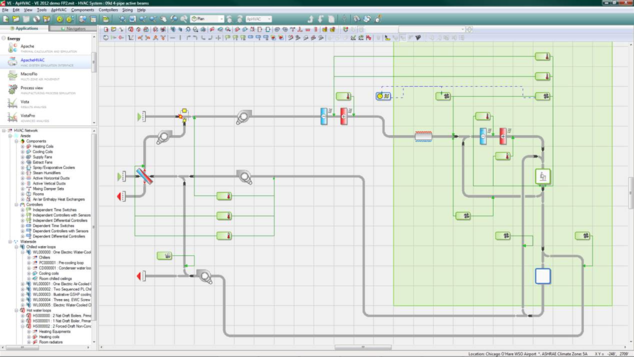
Figure 1 - 9 : The initial model workspace or canvas displays the HVAC system airside schematic and provides a graphical means of selecting, configuring, organizing, and editing airside component and controller objects. While plant equipment other than that associated with water loops is accessed while remaining in this view, this is what we refer to as the airside HVAC or airside network view.
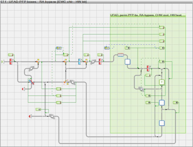
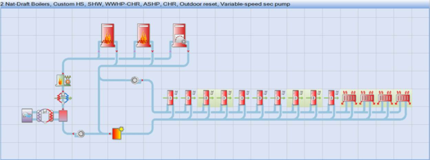
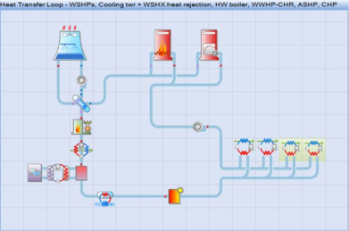
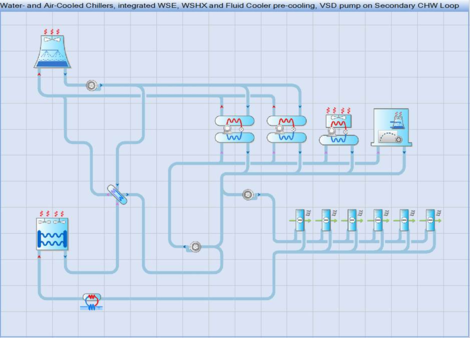
Figure 1 - 10 : There are also three parallel waterside graphic views, as shown above with a range of possible options engaged. These are accessed via the three corresponding toolbar buttons shown below:

Hot water loops

Heat transfer loops

Chilled water loops
These three buttons are toggles that take you back to the airside view when un-clicked.
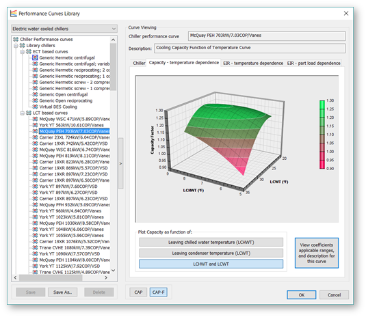
Performance Curve Library
The Performance Curves Library is the first of a set of tools for loading, visualizing, and customizing polynomial fit curve performance data for HVAC equipment. Initially, this covers a large number of generic (entering condenser temperature based) and actual (leaving condenser temperature based) electric water-cooled chiller models. It will later be expanded to include other HVAC plant equipment.
The n ew curves interface provide s exceptional visualization and access to curve parameters. Articulated 3D plot and two different 2D plots are provided for each of Capacity – temperature dependence, EIR – temperature dependence, and EIR – part-load dependence curves.
Figure 1-11: Performance curves library showing a 3D plot of Capacity – temperature dependence for a model-specific LCT-based curve set
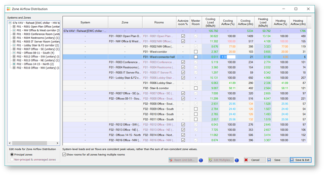
Zone Airflow Distribution
The Zone Airflow Distribution table provides for viewing all zone airflows and for viewing and editing the default distribution of airflow among rooms within each zone.
· As with the outcome of duct sizing and testing & balancing procedures in an actual buildings, airflow from a zone-level VAV box or similar must be appropriately distributed among the rooms that it serves.
· Distribution of air among rooms within a zone for space conditioning is by default according to the relative load in each space.
· Users can override this by editing either the distribution percentages or the individual room airflow values, if desired. (Zone-level airflow overrides are provided in the System Parameters and Zones Tabular Edits dialogs where that airflow is otherwise determined.)
· Rather than directly overwriting user edits, the autosizing process maintains the proportional relationship among rooms in each zone, as established by manual user edits of the default values.
· Ventilation columns are included only when one or more systems has Dual-Inlet Zones. Ventilation air is otherwise distributed as mixed with Primary Air from the air handler for heating and cooling.
· The designation of the Master Room in each zone is also visible and can be edited here.
Figure 1 - 12 : Zone airflow distribution table shown with autosized and manually adjusted airflow distributions within different zones
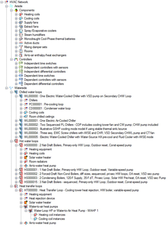
Component browser

Browser show/hide toolbar button.
Figure 1 - 13 : Component browser tree with HVAC network components and controllers.
The component browser provides a listing of all components in the current ApacheHVAC file. This can be used to locate and/or select a particular type of component or controller within a large or complex HVAC network. Selecting the component or controller within the browser causes it to be highlighted on the network in the model space. The browser can also be useful in determining how many of a particular component or controller type are present.
It is not necessary to hide the component browser for most HVAC system networks, as the speed of this has been significantly improved over earlier versions. When working on exceptionally large or complex HVAC networks, if the opening of component and controller dialogs does begin to slow noticeably, the component browser can be turned OFF by clicking the browser show/hide button on the toolbar. This will further increase the speed with which component and controller dialogs open.
Mouse controls
The left mouse button is used for selecting and placing component and controllers. When placing these, the current selection persists until cancelled by clicking the right mouse button. The mouse scroll wheel can be used to zoom in and out of the systems view. The pan function accessed provided by moving the mouse while depressing the scroll wheel.
Mouse/key operations summary
The combined keyboard and mouse actions described in the left column below can be used to complete the corresponding operations listed in all capital letters in the right column.
Selected airside network objects
Drag MOVE
Ctrl + Drag COPY
Ctrl-C COPY TO CLIPBOARD
Ctrl-V PASTE FROM CLIPBOARD (within current HVAC session)
Elements of a selected controller (applies only when a single controller is selected)
Click & Drag MOVE NODE (round sensor bulb or control lead end with arrowhead)
Shift + Drag MOVE CONTROL BOX
DURING “PENCIL” DRAWING
Click on object or in blank cell START NEW PATH
Click object after starting path CONNECT or CREATE JUNCTION
Click bare end after starting path CONNECT or CREATE JUNCTION
Click bare end after starting path CREATE CUSP or 90° BEND
Double-click in a blank cell TERMINATE CURRENT PATH (as bare end)
Ctrl-Z (up to 10 times) UNDO SECTION to PREVIOUS CUSP/OBJECT