8. BSDF Scenarios and Examples
Scenario 1: modify all the glazing to use a BSDF material
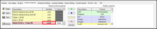
Go into the Surface Properties tab.
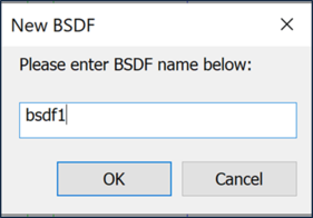
Create a new BSDF property (using the yellow  button). Enter image name (this name cannot contain spaces).
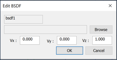
When OK is clicked the Edit BSDF dialog pops up where the BSDF properties can be adjusted and the BSDF is added to the grid.
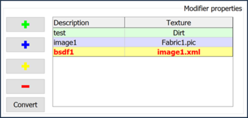
It is expected the xml representing the BSDF is sourced from a 3rd party and is saved to the local machine prior to continuing. Use the Browse button to find the xml file that defines the BSDF and click OK. The BSDF description is now loaded.
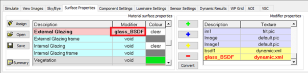
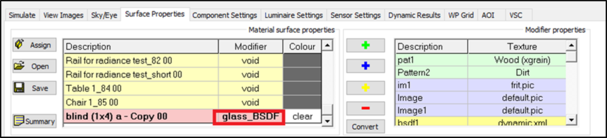
This can now be applied to the glazing by changing the Modifier:
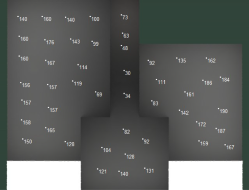
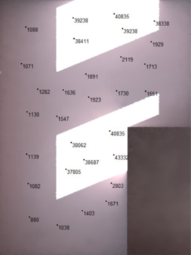
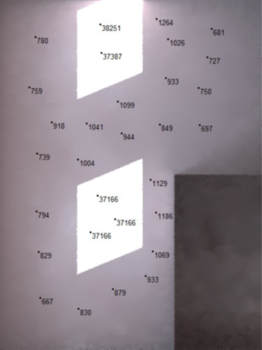
When we now perform a simulation the BSDF definition will be substituted for all the External Glazing - here's a simulation for the ground floor of the test model:
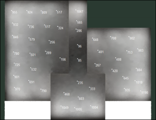
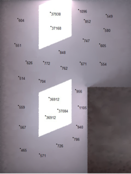
We compare it with the default image (without the BSDF):
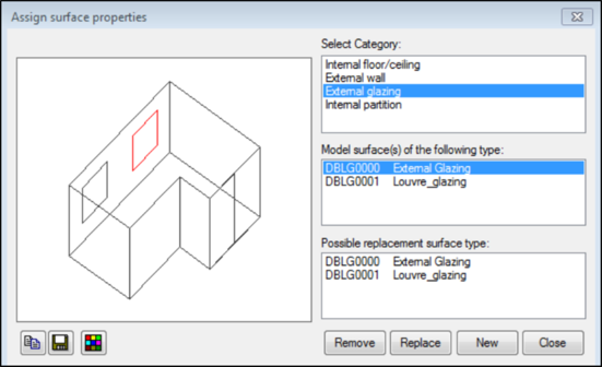
If required, create an alternative replacement surface type using the Assign option. For example, in this zone we have two windows with different glazing.
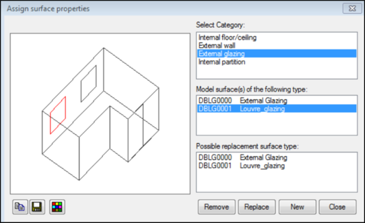
In this example we would assign the BSDF to the Louvre_glazing and not to the External Glazing - i.e. the External Glazing modifier would be void and the Louvre_glazing modifier would be set to glass_BSDF.
Scenario 2: Component to represent a blind added to one of the zones
In this scenario we have to edit the material property for the Component:
Note: the modifier can only see the BSDFs when the material property is set to glass.
The components have to be switched ON (in the Component Settings tab).
When used in this mode the properties for the component are substituted for the BSDF, so it is irrelevant what properties are defined.
Default image with no blind:
Image with solid blind:
Image with BSDF blind:
The two images above look similar but the lux levels at the back of the space are higher for the BSDF blind.