The first activity to carry out is to create a ‘building’. A building consists of floor pans (imported from CAD files in DXF format) and staircases (defined within Simulex).
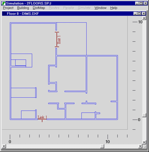
To add a floor, you import a DXF drawing file created with a standard CAD program. However, when you create the DXF file you must delete all information which is not relevant to the building shape - only the walls must be left. All other information such as door swing lines, text and other irrelevant lines must be deleted in advance, otherwise the simulation cannot proceed. Simulex uses the wall lines to define the physical space available for evacuation. Building contents can of course exist on the drawings if the location of those are known in advance, but remember that all physical objects are regarded as immovable. Each new floor plan is assigned, and displayed in, a new window. The contents will obstruct the occupants trying to evacuate. A sample screen display from Simulex is displayed below.
Figure 1: Simple Floor Plan
It is advisable to frequently save the project file which is done in the Project menu. By saving a project, the floor plan drawings, staircases, connections and all other relevant information will be stored under a separate filename. A project file has the extension *.spj.
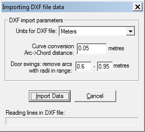
Figure 2: DXF Import Dialog
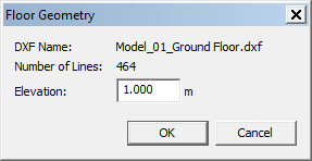
Figure 3: Floor Geometry Dialog
To add a floor, use the Menu Item: Building > Add Floor, which activates the DXF filter. You will need to specify the file name and location. Simulex analyses the file, and then will ask you what units the file is stored in, because this information is not specified in the DXF file (see Figure 2). Normally, this will either be meters or inches. To check if you have used the right units of measurements, you should compare the size of the plan when it is drawn in the display window, to the meters scale drawn on all sides of the plan. If it is displayed at the wrong scale, then you will need to delete the floor plan, using Menu Item: Building > Delete, and then re-import the DXF file with a different scale. Usually, when you have found the correct units, this will be okay for all DXF files created on the same CAD package. Once the DXF import has completed you will be presented with the Floor Geometry dialog (see Figure 3). This will display the name of the DXF, how many lines were imported and what elevation (i.e. height) the floor is at. The height is important for viewing your project in 3D (see 8.5.3). A maximum of 100 floors can be added.
The floor plan is now visible as a small icon in the lower left corner of the main window. Double-click on the icon and the floor plan window will open. The drawing can be enlarged or reduced by using the zoom keys F5 and F6, which will zoom in and out. A distance scale is visible around the floor plan showing the distance in metres.