NECB-2011 Article 8.4.4.10
Type of Heating System:
NECB-2011 Article 8.4.4.10 (1) states that the heating system serving each thermal block of the reference building shall be determined in accordance with Table 8.4.4.8.A.
A selection of primary heating equipment based on the details provided in the NECB standard have been provided in the NECB reference system library. Where appropriate default information has been assigned to the systems, but these should be reviewed and changed as appropriate to meet the specifics of the building undergoing the analysis.
Energy Type:
NECB-2011 Article 8.4.4.10 (4) states that the energy type of the reference building's heating system shall be modeled as being identical to the energy type of the proposed building's heating system.
NECB-2011 Article 8.4.4.10 (5) states that where more than one energy type is used by the proposed building's heating system
a) the heating capacities of the reference building's heating equipment shall match the ratio of the proposed building's heating equipment capacity allocation, and
b) the operating schedule, priority of use and other operational characteristics of the proposed building's use of energy types shall apply.
The NECB reference systems in ApacheHVAC contain a default energy type of natural gas or electricity as appropriate. These should be reviewed by the user to ensure that the fuel type meets the specific configuration of their building.
Number of Boilers:
NECB-2011 Article 8.4.4.10 (6) states that
· where the heating capacity is not greater than 176 kW, the heating plant shall be modeled with one single-stage boiler,
· where the heating capacity is greater than 176 kW and not greater than 352 kW, the heating plant shall be modeled to operate as required by the reference building's load with
o two boilers of equal capacity, or
o a two-staged boiler that operates in stages with a 1:2 ratio,
· where the heating capacity exceeds 352 kW, the heating plant shall be modeled with a boiler that is fully modulating down to 25% of its capacity,
A hot water loop has been included by default to match the ‘two boilers of equal capacity’ requirement. This can be edited to match the requirements specific to the building undergoing the analysis. Note that the default boiler assignment should also be reviewed and updated based on the NECB standard.
Hot Water Pumps:
NECB-2011 Article 8.4.4.10 (6) states that
· The pumping system shall be modeled as a primary system with constant speed operation
· The peak pumping flow rate shall be set considering
o the installed heating plant's capacity
o use of pure water, and
o a l6°C temperature drop
· The pump's operating schedule shall be modeled as being identical to that of the proposed building
The default pumping in the NECB hot water loop has been configured as primary only constant speed with the performance curve as per NECB Article 8.4.4.15.
The power demand of the reference pump is dictated by the performance of the pumping in the proposed as per NECB-2011 Article 8.4.4.15:
· Each hydronic pump of the reference building shall have a total static head and efficiency identical to that of the corresponding pump of the proposed building.
· Where the proposed building uses more than one pump in a given hydronic system, the peak shaft power demand of the reference building's pump shall be modeled as being identical to the combined peak shaft power demand of the proposed building's pumps.
· Where the total static head or efficiency of the proposed building's hydronic pump is not known, the characteristics of the reference building's hydronic pump shall be based on the peak power demand, in W/(L/s), of the proposed building's pump.
· Pump power, P, versus flow rate, V, shall be calculated using one of the equations shown in NECB-2011 Article 8.4.4.15
Thus, the specific pump power input required by the VE will have to be entered manually by the user once they know the performance of the proposed hot water pumps or by using the equations in NECB-2011 Article 8.4.4.15.
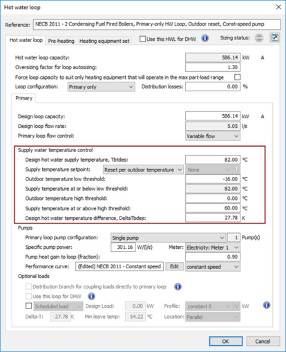
Hot Water Temperature Reset:
NECB-2011 Article 8.4.4.10 (6) states that
The hot water supply temperature shall be reset to
i) 82°C for an outside air temperature of -16°C, and
ii) 60°C for an outside air temperature of 0°C.
This hot water supply temperature reset has been included by default in the example NECB hot water loop.
Figure 1: Default NECB hot water loop supply water temperature control settings
Number of Furnaces:
NECB-2011 Article 8.4.4.10 (7) states that
Where the reference building contains a furnace, it shall be modeled as follows:
· the heating capacity of the furnace shall be the sum of the heating loads of the thermal blocks served by the furnace, multiplied by the applicable oversize factor
· where the heating capacity is not greater than 66 k W, the furnace shall be modeled with two stages of equal capacity, and
· where the heating capacity is greater than 66 kW, the furnace shall be modeled with a number of stages equal to its capacity divided by 66 kW and rounded up to the nearest integer.
A library of NECB furnaces has been provided with the NECB systems.
Part Load Performance:
NECB-2011 Article 8.4.4.10 (8) states that
Heating equipment performance characteristics as a function of part-load shall be modeled in accordance with the part-load performance curves found in Table 8.4.4.22.
A selection of heating equipment has been provided in the NECB systems library with part load conditions as per Article 8.4.4.22, namely:
· Gas fired Boilers – condensing, non-condensing and modulating (Generic Heat Sources)
· Oil fired Boilers – condensing, non-condensing and modulating (Generic Heat Sources)
· Gas fired warm air Furnace – atmospheric & modulating (Generic Heat Sources)
· Gas fired duct Furnace – atmospheric & modulating (Generic Heat Sources)
· Oil fired warm air Furnace – atmospheric & modulating (Generic Heat Sources)
· Oil fired duct Furnace – atmospheric & modulating (Generic Heat Sources)