1.3.1 Hydronic Radiant Slab Zones
Proper modeling of the slab and hydronic tubing is essential, as this is the heat transfer path to and from the water. This is particularly important in the case of a chilled slab, given that this heat transfer will ultimately determine the cooling capacity and resulting thermal comfort under peak conditions. Using a standard slab construction will tend to overestimate heat transfer to and from the hydronic loops. Conversely, the model should be constrained only by slab properties, controlled temperature and flow rate of the water, and the capacity of the heating and/or cooling water sources.
· The radiant slab zone should be represented in the model with a minimal non-zero interior volume. While it must have some volume in order to be simulated as a thermal space in the model, the air volume inside the slab zone should be minimized so that it is effectively removed from the heat transfer modeling.
o When inner volume representation is not applied in ModelIT, this can be accomplished by simply drawing a very thin zone—e.g., 0.01 inch or 0.1 mm, or similar height. The construction thickness for the slab material will still me modeled, but will not be visually represented and will not contribute to the height of the exterior walls or overall building.
o If inner volume representation is used in ModelIT, then the slab zone should be drawn as representing just the slab thickness that is above the centerline of the hydronic tubing. The total thickness of slab zone top construction (the “ceiling” of the slab zone) should then be very slightly less than the actual thickness from the tubing centerline to the finished floor or equivalent surface above. The bottom portion of the slab—below the tubing center line—should then be set by the top layer in the construction for the ceiling of the space below (e.g., a return plenum or occupied space under the radiant slab).
For example, in IP units, a 6” thick radiant floor slab with hydronic tubing 2” from the top surface and a room below would have the following dimensions and constructions:
§ Slab zone height = 2”
§ Slab zone “ceiling” overall construction thickness = 1.99”
§ The top layer (outermost) of the construction for the “ceiling” of the space below should be concrete of appropriate thermal characteristics with layer thickness = 4”
§ If the slab construction, including any insulating layers, is in direct contact with the earth:
- The innermost layer (bottom layer in the list of construction layers) of the ground-contact floor construction should be concrete of appropriate thermal characteristics with layer thickness = 4”
- The second from the outermost layer (top layer in the list of construction layers) of the ground-contact floor construction should be approximately 36” of soil to represent the thermal mass with which the hydronic slab—whether insulated or not—will interact.
- The outermost layer (top layer in the list of construction layers) of the ground-contact floor construction should be a U-value adjustment layer (created with the U-value adjustment tool) to appropriately represent the sum of all potential heat transfer paths through the ground to the outside air (see below).
· If the conditioned slab is in contact with the ground, user the Ground-contact U-value adjustment facility within the Ground-contact/Exposed Floors section of the constructions database (ApCdb) to add an appropriate U-value adjustment layer. Both EN-ISO and F-Factor methods are provided. Whether there is to be perimeter or under-slab insulation in the project, this facility will add an additional layer of insulation in the construction to represent the resistance of the average path from the average underside of your building to the outside air. This layer is best added beyond the 30” (0.75 m) of earth normally included in ground-contact constructions. For hydronic slabs—especially if uninsulated below—the thermal mass of this soil is important with to include adjacent to the floor.
· The inside surface for both the slab top and bottom (ceiling and floor, which will be the ceiling of the room below for non-ground-floor stories of the building) need to have internal air-film resistance set to 0.0001 ft2-hr-F/Btu (or 0.0001 m2K/W, effectively zero, but not zero). This facilitates modeling the water in direct contact with the construction.
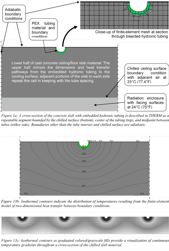
· Conductivity for the concrete material in slab top and bottom constructions should be reduced (adjusted to an appropriate lower value) to account for the spacing and depth of the tubes within the slab, plus the resistance of the PEX tubing wall. This is best done with a 2D finite-element model of just two tubes in a cross-section of the slab top and slab bottom using LBNL’s free THERM tool. This tool provides a quick and accurate means of determining an overall U-value for the combination of all heat-transfer paths between the slab surface and the water in the tubes. Typically, depending upon hydronic tube material, depth, and spacing, the conductivity value for the concrete material will need to be reduced about 20 to 60%---i.e., to about 40 to 80% of its initial value. Whereas the unadjusted value would over-predict heat transfer, too small a value will under-predict it.
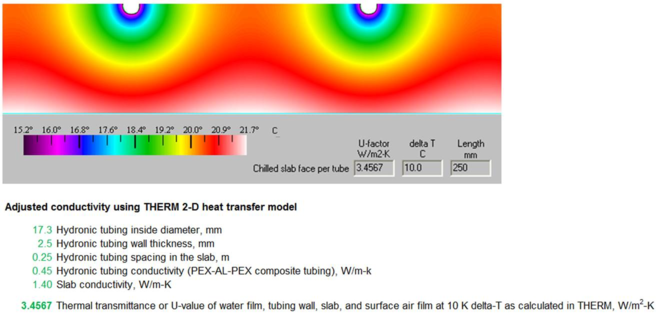
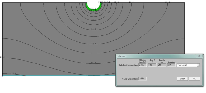
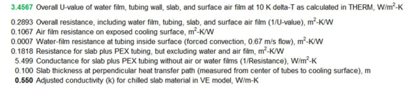
The THERM model and spreadsheet calculations above are used to determine the correct adjusted conductivity for the concrete slab or other material in which the hydronic tubing is embedded. The THERM model is relatively simple and the spreadsheet calculations are simply used to convert U-value to resistance, then subtract the resistance of the water film in the tube and air film on the exposed surface, convert resistance to conductance, and finally use this to calculate the adjusted conductivity value for the concrete material. This final number will be entered into the concrete layer of the construction in the VE and will account for the tube material, diameter, depth from the surface, and spacing within the slab.
The following excerpt from Simulation of Radiant Cooling Performance with Evaporative Cooling Sources
(T. Moore, May 2008; Center for the Built Environment) provides further explanation of the simple slab and hydronic tube model preparation in THERM. Following that within this appendix is a section (12.2.2) on setting up hydronic loops and controls for radiant slabs in ApacheHVAC. Additional information on both of these topics can be found in Simulation of Radiant Cooling Performance with Evaporative Cooling Sources, available from the UC Berkeley Center for the Built Environment at: