The meanings of the Vista variables are defined below. Any variables appearing in Vista that are not listed here are obsolete variables generated by earlier versions of the software, and are identified as such by the tag ‘(obs)’ in the variable name.
Weather Variables
Dry-bulb temperature: The external air temperature measured in a standard meteorological screen.
Wet-bulb temperature: The temperature measured by a wet-bulb thermometer in a standard meteorological screen.
External dew-point temperature: The dew-point temperature of the external air (the temperature at which the air would become saturated if cooled)
Wind direction: The direction from which the wind is blowing, measured clockwise from true north.
The wind speed measured at a height of 10m above the ground.
Direct radiation: The intensity (irradiance) of the solar beam emanating from the sun's disc and the region of sky immediately around it, measured perpendicular to the beam.
Diffuse radiation: The intensity (irradiance) of solar radiation emanating from the sky, excluding that portion immediately around the sun, measured on the horizontal plane.
Global radiation: The intensity (irradiance) of solar radiation falling on the horizontal plane.
Solar altitude: The angular elevation of the centre of the sun's disc above the horizontal plane.
Solar azimuth: The horizontal angle between the vertical plane containing the centre of the sun's disc and the vertical plane running in a true north-south direction, measured clockwise from true north.
Cloud cover: The proportion of the sky covered by cloud.
Atmospheric pressure: The pressure exerted by the atmosphere.
External relative humidity: The relative humidity of the external air (water vapour pressure expressed as a percentage of saturated vapour pressure)
External moisture content: The moisture content of the external air (mass of water vapour expressed as a fraction of mass of dry air)
Model Level Variables
These variables are accessed by clicking on ‘Model’ in the browser. They are organized in three groups: Loads, Energy and Carbon.
Loads
Room heating plant sens. load: The sum of the room heating plant sensible loads for all rooms in the building.
ApHVAC room units heating load: When an ApacheHVAC system is in use, the sum of the heating loads on all radiators and direct acting heaters.
Room hum. plant load: The sum of the room humidification plant sensible loads for all rooms in the building.
System air heating load: The total of the system air heating loads for all Apache Systems.
Aux vent heating load: The total auxiliary ventilation heating load for the building (handled by Apache Systems).
ApHVAC heating coils load: When an ApacheHVAC system is in use, the sum of the heating loads on all heating coils.
ApHVAC steam humidifiers load: When an ApacheHVAC system is in use, the sum of the loads on all steam humidifiers.
Boilers load: The sum of the loads (outputs) for all boilers (in both Apache Systems and ApacheHVAC systems).
ApHVAC heat pumps load: When an ApacheHVAC system is in use, the sum of the loads on all heat pumps.
Room cooling plant sens. load: The sum of the room cooling plant sensible loads for all rooms in the building.
ApHVAC room units cooling load: When an ApacheHVAC system is in use, the sum of the cooling loads on all direct acting coolers and chilled beams.
Room dehum. plant load: The sum of the dehumidification plant sensible loads for all rooms in the building.
System air sens. clg load: The total of the system air sensible cooling loads for all Apache Systems.
System air lat. clg. load: The total of the system air latent cooling loads for the building (handled by Apache Systems).
Aux vent sens. clg. load: The total auxiliary ventilation sensible cooling load for the building (handled by Apache Systems).
Aux vent lat. clg. load: The total auxiliary ventilation latent cooling loads for the building (handled by Apache Systems).
ApHVAC cooling coils load: When an ApacheHVAC system is in use, the sum of the cooling loads on all cooling coils (including any latent component).
Chillers load: The sum of the loads (outputs) for all chillers (in both Apache Systems and ApacheHVAC systems).
ApHVAC recovered sensible heat: When an ApacheHVAC system is in use, the net sensible heat (or if negative, net sensible cooling) recovered by heat recovery components.
ApHVAC recovered latent heat: When an ApacheHVAC system is in use, the net latent heat (or if negative, net latent cooling) recovered by heat recovery components.
DHW heating demand: The total DHW heating demand at the hot water outlets (i.e. excluding pipe and tank losses) calculated on the basis of a 50K temperature rise from the cold water main.
CH[C]P generated heat: The heat contributed by the CHP plant, if present. This heat is assumed to be input at the same point as heat from boilers – i.e. upstream of distribution losses.
Energy
Boilers energy: The total energy consumption for boilers (in both Apache Systems and ApacheHVAC systems).
Chillers energy: The total energy consumption for chillers (in both Apache Systems and ApacheHVAC systems).
ApHVAC direct acting heaters energy: When an APhvac system is in use, the energy consumption for direct acting heaters.
ApHVAC direct acting coolers energy: When an APhvac system is in use, the energy consumption for by direct acting coolers (direct acting heaters working in cooling mode).
ApHVAC heat pumps energy: When an APhvac system is in use, the energy consumption for heat pumps.
ApHVAC fans energy: The total energy consumption for fans (in both Apache Systems and ApacheHVAC systems).
ApHVAC pumps energy: The total energy consumption for central plant pumps (in both Apache Systems and ApacheHVAC systems).
ApHVAC HR & spray pumps energy: When an APhvac system is in use, the total energy consumption for heat recovery components and spray pumps.
Ap Sys fans/pumps/ctrls energy: Energy consumed by fans, pumps and controls within Apache Systems. Includes auxiliary energy, chiller heat rejection pump energy, and pump energy associated with DHW and solar water heating systems.
PV generated electricity: Electricity generated by a photovoltaic system, if present. Negative by convention.
Wind generated electricity: Electricity generated by a wind turbine, if present. Negative by convention.
CHP energy consumption: The energy consumed by the CHP plant, if present. This includes energy associated with space heating, domestic hot water and absorption cooling.
CHP generated electricity: Electricity generated by a CHP system, if present. Negative by convention.
System electricity: The system electrical energy consumption.
System <fuel>: The system energy consumption associated with the named fuel. In the case of grid displaced electricity includes a negative contribution from any electricity generated by PV, wind turbine and CHP systems.
Total system energy: The total system energy consumption, calculated as the sum of the energy consumptions for system components, or alternatively as the sum of system fuel consumptions. Includes a negative contribution from any electricity generated by PV, wind turbine and CHP systems.
Equipment electricity: Electrical energy consumption associated with equipment gains (internal gains excluding lighting). This variable is not reduced by electricity generation by PV, wind turbines and CHP systems
Equipment <fuel>: Energy consumption associated with equipment gains (internal gains excluding lighting) using the named fuel. This variable is not reduced by electricity generation by PV, wind turbines and CHP systems
Total equipment energy: Total energy consumption associated with equipment gains (internal gains excluding lighting). This variable is not reduced by electricity generation by PV, wind turbines and CHP systems
Lights electricity: Electrical energy consumption associated with lighting. This variable is not reduced by electricity generation by PV, wind turbines and CHP systems.
Lights <fuel>: Energy consumption associated with lighting. This variable is not reduced by electricity generation by PV, wind turbines and CHP systems.
Total lights energy: Total energy consumption associated with lighting. This variable is not reduced by electricity generation by PV, wind turbines and CHP systems.
Total electricity: Total electrical energy consumption for systems, lights and small power. This variable is not reduced by electricity generation by PV, wind turbines and CHP systems.
Total <fuel>: Total energy consumption for systems, lights and small power using the named fuel. In the case of the ‘fuel’ grid displaced electricity – electricity generated by PV, wind turbine and CHP systems – the variable is negative by convention.
Total energy: Total energy consumption for systems, lights and small power. Includes a negative contribution from any electricity generated by PV, wind turbine and CHP systems.
Carbon
System elec. CE: Carbon emissions produced by system electrical consumption.
System <fuel> CE: Carbon emissions produced by consumption of the named fuel by systems. In the case of grid displaced electricity includes a negative contribution from any electricity generated by PV, wind turbine and CHP systems.
Total system CE: Total carbon emissions produced by systems. Includes a negative contribution from any electricity generated by PV, wind turbine and CHP
Equipment elec. CE: Carbon emissions produced by electrical energy consumption associated with equipment gains (internal gains excluding lighting).
Equipment <fuel> CE: Carbon emissions associated with equipment gains (internal gains excluding lighting) powered by the named fuel.
Total equipment CE: Total carbon emissions associated with equipment gains (internal gains excluding lighting).
Total electricity CE: Total carbon emissions associated with electrical energy consumption for systems, lights and small power. This variable is not reduced by electricity generation by PV, wind turbines and CHP systems.
Total <fuel> CE: Total carbon emissions associated with consumption of the named fuel. In the case of grid displaced electricity – electricity generated by PV, wind turbine and CHP systems – the variable is negative by convention.
Total CE : Total carbon emissions for the building and its systems. Includes a negative contribution from any electricity generated by PV, wind turbine and CHP systems.
Total CE ex equip : Total carbon emissions for the building and its systems, excluding emissions associated with equipment (which do not feature in the emission calculations for the UK Building Regulations). Includes a negative contribution from any electricity generated by PV, wind turbine and CHP systems.
Apache System Variables
These variables are accessed by selecting the Systems browser and clicking on one of the Apache Systems in the list (but not an ApacheHVAC system if one is present). They are organized in three groups: System, Energy and Carbon.
Note that if results from a linked ApacheHVAC system were requested (see Section 7), rooms served by such an ApacheHVAC system do not contribute to the variables listed here.
System
Room heating plant sens. load: The sum of the room heating plant sensible loads for all rooms served by the system.
Room hum. plant load: The sum of the room humidification plant sensible loads for all rooms served by the system.
System air heating load: The (non-negative) sensible heat required to raise the temperature of outside air to the specified supply temperature. Only applies when the supply temperature is specified as 'Temperature From Profile'.
Aux vent heating load: For Auxiliary Ventilation air supplies, the (non-negative) sensible heat required to raise the temperature of outside air to the temperature specified. Only applies to those Auxiliary Ventilation air exchanges for which the supply temperature is specified as 'Temperature From Profile'.
DHW heating demand: The DHW heating demand at the hot water outlets (i.e. excluding pipe and tank losses) calculated on the basis of a 50K temperature rise from the cold water main.
DHW boiler load: The DHW heating load at the boiler, after allowing for pipe and tank losses and any contribution from a solar water heating system.
DHW solar heating system input: The heat input from the solar heating system, if present. This is the amount by which the DHW boiler load is reduced by preheating of the cold water supply by the solar water heating system.
DHW solar htg system tank temp: The mean temperature of water in the solar heating system tank, if present.
DHW solar heat input: The heat input from the solar panel (if present) to the solar heating system storage tank.
Boiler load: The load on the Apache System boiler, calculated as the sum of the room heating plant and air heating loads (both system and aux mech vent) met by the system, with an adjustment applied for distribution losses.
CHP heat contribution: The heat contributed to the Apache System by the CHP system, if present. This heat is assumed to be input at the same point as heat from the boiler – i.e. upstream of distribution losses.
Room cooling plant sens. load: The sum of the room cooling plant sensible loads for all rooms served by the system.
Room dehum. plant load: The sum of the room dehumidification plant sensible loads for all rooms served by the system.
System air sens. clg. load: The (non-negative) sensible cooling required to cool the outside air to the specified supply temperature. Only applies when the supply temperature is specified as 'Temperature From Profile'.
System air lat. clg. load: The (non-negative) latent load incurred in lowering the temperature of outside air to the specified supply temperature, calculated on the basis of a maximum off-coil percentage saturation of 90%. Only applies when the supply temperature is specified as 'Temperature From Profile'.
Aux vent sens. clg. load: For Auxiliary Ventilation air supplies, the (non-negative) sensible cooling required to lower the temperature of outside air to the temperature specified. Only applies to those Auxiliary Ventilation air exchanges for which the supply temperature is specified as 'Temperature From Profile'.
Aux vent lat. clg. load: For Auxiliary Ventilation air supplies, the (non-negative) latent load incurred in lowering the temperature of outside air to the temperature specified, calculated on the basis of a maximum off-coil percentage saturation of 90%. Only applies to those Auxiliary Ventilation air exchanges for which the supply temperature is specified as 'Temperature From Profile'.
Chiller load: The load on the Apache System chiller, calculated as the sum of the room cooling plant and air cooling loads (both system and aux mech vent, sensible plus latent) met by the system, with an adjustment applied for distribution losses.
System air flow rate: The total volume flow rate of air supplied by the system (excluding auxiliary mechanical ventilation). In the case of a system of type Generic, this is the total outdoor air supply.
System air supply temperature: The temperature of air supplied by the system to the rooms.
System air supply moisture content: The moisture content of air supplied by the system to the rooms.
Aux vent flow rate: The total volume flow rate of auxiliary ventilation supplied by the system.
Energy
Boiler energy: The energy consumption of the boiler.
Boiler pump energy: The energy consumption of the boiler pumps.
Chiller energy: The energy consumption of the chiller.
Chiller heat rej. pump energy: The energy consumption of chiller heat rejection pumps and fans.
System auxiliary energy: The auxiliary energy consumption of the system.
DHW & solar heating pump energy: The energy consumed by DHW and solar heating system pumps.
Carbon
Boiler CE: Carbon emissions produced by the energy consumption of the boiler.
Chiller CE: Carbon emissions produced by the energy consumption of the chiller.
Chiller heat rej. CE: Carbon emissions produced by the energy consumption of chiller heat rejection pumps and fans.
System auxiliary energy CE: Carbon emissions produced by the auxiliary energy consumption of the system.
DHW & solar heating pump CE: Carbon emissions produced by the energy consumed by DHW and solar heating system pumps.
Room Variables
These variables are accessed by selecting a room or a set of rooms in the browser or the building graphic.
Note that a room may be served by either an Apache System or an ApacheHVAC system, if one is present (see Section 7).
Air temperature: The mean temperature of the air in the room.
Dry resultant temperature: The mean of the room air and mean radiant temperatures.
Environmental temperature: A 2:1 weighted average of mean radiant temperature and air temperature
Mean radiant temperature: The uniform temperature of an imaginary enclosure in which radiant heat exchange with the human body would equal the radiant heat exchange occurring in the room.
Dew-point temperature: The dew-point temperature of the air (the temperature at which the air would become saturated if cooled).
People dissatisfied: An index that predicts the percentage of occupants expressing dissatisfaction with the room thermal environment.
Predicted mean vote: An index that predicts the mean value of the votes of a large group of occupants on the following 7-point thermal sensation scale: +3 hot +2 warm +1 slightly warm 0 neutral -1 slightly cold -2 cool -3 cold
Comfort index: An index predicting comfort within the space based on the following scale:
1: very cold, danger
2: cold, shivering
3: cool, unpleasant
4: cool, acceptable
5: slightly cool/acceptable
6: comfortable, pleasant/cool
7: comfortable, pleasant
8: comfortable, pleasant/warm
9: slightly warm/acceptable
10: warm, acceptable
11: warm, unpleasant
12: hot, very uncomfortable
13: very hot, danger
14: unoccupied
15: non-sedentary
Relative humidity: The water vapour pressure of the air expressed as a percentage of the saturation vapour pressure.
Moisture content: The water vapour content of the air (mass of water vapour expressed as a fraction of mass of dry air).
Room CO2 concentration: the volumetric concentration of carbon dioxide in the room (parts per million).
Space conditioning sensible: Sensible heat (or if negative, cooling) supplied to the room by its Apache System or ApacheHVAC system. This consists in general of two terms: a contribution from the room conditioning plant (or HVAC radiators, direct acting heaters and chilled beams) and a contribution from the system air supply.
Steady state heating plant load: Heating plant sensible load calculated under steady state conditions by CIBSE Loads (heating plant sensible load is calculated from this by application of an intermittency factor).
Heating plant sensible load: Sensible heating (non-negative) supplied to the room by its Apache System room conditioning plant or ApacheHVAC room units (radiators, direct acting heaters and chilled beams)
Cooling plant sensible load: Sensible cooling (non-negative) supplied to the room by its Apache System room conditioning plant or ApacheHVAC room units (radiators, direct acting heaters and chilled beams).
Internal gain: Sensible heat (or if negative, cooling) supplied to the room by equipment, lights, people and other heat sources specified as Internal Gains.
Solar gain: Solar radiation absorbed on the internal surfaces of the room, plus solar radiation absorbed in glazing and transferred to the room by conduction.
External conduction gain: Heat conducted into (or if negative, out of) the room through the internal surfaces of externally exposed elements, including ground floors.
Internal conduction gain: Heat conducted into (or if negative, out of) the room through the internal surfaces of wall partitions, internal floors/ceilings and elements with adjacent condition 'Temp from profile' or 'Outside air with offset temp.'.
Conduction gain: Combined external and internal conduction gain (CIBSE Loads only)
Air system input sensible: The sensible heat gain (or if negative loss) from the air system. In the case of an Apache System of type Generic, this is the sensible gain from the (possibly conditioned) outdoor air supply.
Aux vent gain: The sensible heat gain (or if negative loss) from Auxiliary Ventilation air exchanges.
Natural vent gain: The sensible heat gain (or if negative loss) from Natural Ventilation air exchanges.
Infiltration gain: The sensible heat gain (or if negative loss) from Infiltration air exchanges.
MacroFlo ext vent gain: The sensible heat gain (or if negative loss) from MacroFlo-calculated air flows entering the room from the external environment.
MacroFlo int vent gain: The sensible heat gain (or if negative loss) from MacroFlo-calculated air flows entering the room from adjacent rooms.
System air supply: The air supply associated with the system. In the case of an Apache System of type Generic, this is the outdoor air supply.
Aux mech vent: The flow of air into the room from Auxiliary Mechanical Ventilation air exchanges.
Natural vent: The flow of air into the room from Natural Ventilation air exchanges.
Infiltration: The flow of air into the room from Infiltration air exchanges.
MacroFlo ext vent: The sum of MacroFlo-calculated air flows entering the room from the external environment.
MacroFlo int vent: The sum of MacroFlo-calculated air flows entering the room from adjacent rooms.
Space conditioning latent: The latent heat equivalent of water vapour added to (or if negative, removed from) the room by its Apache System or ApacheHVAC system. This consists in general of two terms: a contribution from the room conditioning plant (or HVAC radiators, direct acting heaters and chilled beams) and a contribution from the system air supply.
Humidification plant load: The (non-negative) latent heat equivalent of water vapour added to the room by its Apache System room conditioning plant (if present).
Dehumidification plant load: The (non-negative) latent heat equivalent of water vapour removed from the room by its Apache System room conditioning plant (if present).
Cooling + dehum plant load: the sum of cooling and dehumidification plant loads.
Internal latent gain: The latent heat equivalent of water vapour added to (or if negative, removed from) the room by equipment, people and other heat sources specified as Internal Gains.
Equipment latent gain: The internal sensible gain from equipment.
People latent gain: The internal sensible gain from people.
Number of people: The number of people in the room.
DHW heating demand: The DHW heating demand at the room’s hot water outlets (i.e. excluding pipe and tank losses) calculated on the basis of a 50K temperature rise from the cold water main.
Air system input latent: The latent heat equivalent of water vapour added to (or if negative removed from) from the space by the air system. In the case of an Apache System of type Generic, this is the latent gain from the (possibly conditioned) outdoor air supply.
Vent/infiltr. latent gain: The combined latent heat gain (or if negative loss) from Auxiliary Mechanical Ventilation, Natural Ventilation and Infiltration air exchanges.
Aux vent lat gain: The latent heat gain (or if negative loss) from Auxiliary Ventilation air exchanges.
Natural vent lat gain: The latent heat gain (or if negative loss) from Natural Ventilation air exchanges.
Infiltration vent lat gain: The latent heat gain (or if negative loss) from Infiltration air exchanges.
MacroFlo ext vent lat gain: The latent heat gain (or if negative loss) from MacroFlo-calculated air flows entering the room from the external environment.
MacroFlo int vent lat gain: The latent heat gain (or if negative loss) from MacroFlo-calculated air flows entering the room from adjacent rooms.
Convective room plant load: The convective component of the sensible heat input from Apache System room conditioning plant or ApacheHVAC room units (provided as an input to MicroFlo).
Convective lighting gain: The convective component of the sensible heat input from lights (provided as an input to MicroFlo).
Convective equipment gain: The convective component of the sensible heat input from equipment (provided as an input to MicroFlo).
Convective people gain: The convective component of the sensible heat input from people (provided as an input to MicroFlo).
Surface Variables
These variables are accessed by selecting a room surface or opening (window or door) in the browser or the building graphic.
Surface temperature: The temperature of the inner surface of the element.
Incident solar flux: The solar flux (irradiance) incident on the surface.
Incident solar power: The solar power (area-integrated irradiance) incident on the surface.
Volume flow in: The volume flow entering through a MacroFlo opening.
Volume flow out: The volume flow leaving through a MacroFlo opening.
Mass flow in: The mass flow entering through a MacroFlo opening.
Mass flow out: The mass flow leaving through a MacroFlo opening.
Eqv area: The equivalent area of a MacroFlo opening.
VE-Compliance Variables
These Model Level variables are created following a VE-Compliance Simulation for all of the available VE-Compliance regulation frameworks.
VE-Compliance Energy
NCM heating energy: The energy consumed by all heat sources (boilers, heat pumps, CHP, etc…) for the purpose of space heating. This is influenced by the system load, delivery losses, heat generator efficiency and, where applicable, ADL2A table 2 correction factors.
NCM cooling energy: The energy consumed by all chillers for the purpose of space cooling. This is inclusive of the system load, delivery losses, chiller efficiency, heat rejection pump and fan power and, where applicable, ADL2A table 2 correction factors. Further, in the case of absorption chillers, this includes the energy consumed by the heat source (CHP/Boilers).
NCM auxiliary energy: Auxiliary energy accounts for the energy used by controls, pumps and fans associated with the HVAC systems. This is influenced by the NCM system type, steady state heating/cooling load, system parameters such as fan power and pump type and, where applicable, ADL2A table 2 correction factors. A full description of the auxiliary energy calculation method is given in the NCM Modeling Guide for the respective compliance framework.
NCM Lighting energy: The energy consumed by all electric lighting in the building. This is influenced by the NCM activities assigned, the lighting power density, light controls such as photoelectric dimming or occupancy sensing, dimming profiles and, where applicable ADL2A table 2 correction factors.
NCM DHW energy: The energy consumed by all heat sources (boilers, heat pumps, CHP, etc…) for the purpose of supplying domestic hot water. This is influenced by the efficiency of the heat generator(s), delivery losses, storage and secondary circulation losses, solar thermal DHW heat input, and, where applicable, ADL2A table 2 correction factors.
NCM total energy (ex renewables): The total energy consumption for the building across all of the Part L end uses: NCM Heating, NCM Cooling, NCM auxiliary energy, NCM Lighting energy, and NCM DHW energy. No allowance is made for electricity offset through the use of renewables i.e. CHP, Wind Power, or Photovoltaics.
NCM heat pump heating energy: The energy consumed by heat pumps for the purpose of space heating and DHW. This is influenced by the system load, delivery losses, heat generator efficiency and, where applicable, ADL2A table 2 correction factors.
VE-Compliance Carbon
NCM heating CE: The total carbon emissions arising from space heating. This is the product of the energy consumed by each heat generator for space heating times the Carbon Emission Factor for its respective fuel.
NCM cooling CE: The total carbon emissions arising from space cooling. This is the product of the energy consumed by each chiller for space cooling times the Carbon Emission Factor for its respective fuel.
NCM auxiliary CE: The total carbon emissions arising from auxiliary energy . This is the product of the NCM auxiliary energy consumption times the Carbon Emission Factor for electricity.
NCM lighting CE: The total carbon emissions arising from NCM lighting energy. This is the product of the NCM lighting energy consumption times the Carbon Emission Factor for its fuel (normally electricity).
NCM DHW CE: The total carbon emissions arising from domestic hot water provision. This is the product of the energy consumed by each heat generator for domestic hot water times the Carbon Emission Factor for its respective fuel.
NCM total CE (ex renewables): The total carbon emissions for the building across all of the Part L end uses: NCM Heating CE, NCM Cooling CE, NCM auxiliary CE, NCM Lighting CE, and NCM DHW CE. No allowance is made for carbon offset through the use of renewables i.e. CHP, Wind Power, or Photovoltaics.
NCM heat pump heating CE: The total carbon emissions arising from space heating and domestic hot water provided by heat pumps. This is the product of the energy consumed by each heat pump for space heating and DHW times the Carbon Emission Factor for its respective fuel.
ApacheHVAC Results
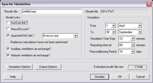
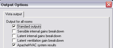
To view HVAC results in Vista, the ApacheHVAC link must be selected on the Apache Simulation dialog and ApacheHVAC system results must be selected in Output Options:
In Vista, select Systems in the Model browser, then the ApacheHVAC system will be visible as the last System in the list, called ‘ApHVAC: <asp file>’. Selecting this will give you a view of the ApacheHVAC network schematic.
The asp filename will be appended to the Vista filename in the title bar.
Component Variables
This is the default mode and is entered by choosing ‘HVAC – Select Components’ from the interrogation dropdown list.
Results can be viewed for only a subset of all the ApacheHVAC components, namely coils, fans and rooms. Those components for which results are available are listed in the browser and selectable either there or on the schematic. Other components on the schematic are not selectable.
As in ApacheHVAC itself, multiple components can be selected by drawing a rectangle, or by using Ctrl-click.
For room components, all the room variables as listed in Section 6.4 are applicable. For coil and fan components the only variable that is applicable is “Air Enthalpy addition”, which represents the load across the component.
Node Variables
This mode is entered by choosing ‘HVAC – Select Nodes’ from the interrogation dropdown list. Nodes represent ducts in the network, and appear as numbers (10, 20, 30…). A long duct will have its node number repeated at each end.
Nodes appear only on the schematic and not in the browser.
To select a node simply click on or near its number, or anywhere on the duct. In a complex network you may find that you have to select within the nearest component, rather than on the node number, to home in on the right node.
As for components, multiple nodes can be selected by drawing a rectangle, or by using Ctrl-click.
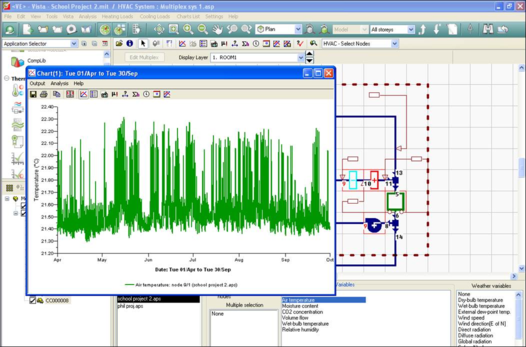
The variables that are available for Nodes are: Mass Flow, Air Temperature, Moisture Content, CO2 Concentration, Volume Flow, Wet-bulb Temperature and Relative Humidity.
Multiplex Results
Results of any Multiplexed ApacheHVAC system can be viewed in Vista as normal. Select Components or Nodes within the Multiplex to view detailed results. Click within the Multiplex then change the Layer dropdown to the layer you are interested in.
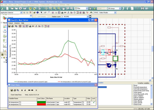
To view the results for multiple layers on the same graph use the Lock Variables tool then switch layer. Lock the results for as many layers as required in this way.