Direct acting units, radiators, and chilled ceilings can be added to spaces for heating and/or cooling purposes. Room units can be added to spaces contained within HVAC zones as well as directly to spaces in an un-zoned model. It is recommended that users work with Room components within ApHVAC, instead of Zone components, when large numbers of room units are to be implemented as editing of the units will be quicker and more efficient.
Direct Acting Heater/Cooler

Toolbar button for direct acting heater/coolers list
Direct acting heaters are intended to represent any room unit with negligible thermal capacity. Unlike radiators, direct acting units can be used to heat or cool a space. Cooling is achieved by entering a negative value for the output (corresponding to either minimum or maximum sensed signal) in the room unit controller dialog.
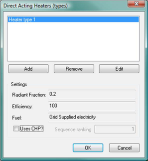
The Direct Acting Heaters dialog allows you to create a set of direct acting heater types for placement in the building. Direct acting heaters can utilize CHP to provide a base load.
Figure 5 - 1 : Direct acting heaters list
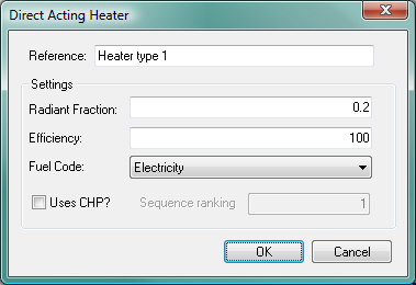
Figure 5 - 2 : Direct acting heater dialog
Reference
Enter a description of the component. The reference is limited to 100 characters. It is for your use when selecting, organizing, and referencing any component or controllers within other component and controller dialogs and in the component browser tree. These references can be valuable in organizing and navigating the system and when the system model is later re-used on another project or passed on to another modeler. Reference names should thus be informative with respect to differentiating similar equipment, components, and controllers.
Radiant Fraction
Enter the radiant fraction of the heat emitted (or cooling effect) from the device. See Table 13 in Apache Tables guide for typical values.
Efficiency
Enter efficiency for the direct acting heater.
Uses CHP?
Tick this box to indicate that the heater can accept heat input from a CHP system (if present).
Sequence ranking
Sequence ranking determines the sequence in which the loads on various heat sources will be addressed by CHP-supplied heat. The loads assigned to heat sources with low values of this parameter will be first in line to receive heat from the CHP. If two heating sources have the same sequence ranking, they will be served simultaneously, with the CHP input supplying the same fraction of the heating load for both.
Hot Water Radiators
In ApacheHVAC, the term “Radiators” covers a broad range of hydronic heating devices placed directly in conditioned spaces. These generally include cast-iron radiators, radiant panel heaters, fin-tube convectors, and so forth. Whether mainly radiative or purely convective heating units, the common thread is that all room units are independent of the airside network and airside components; they directly interact only with the conditioned space and the plant equipment.
Radiator room units can also be used as a hydronic loop within a heated slab zone, but care should be taken in such cases to appropriately define the “type” using parameters that will represent the properties of just the hydronic loop within the slab.

Toolbar button for hot water radiator types dialog
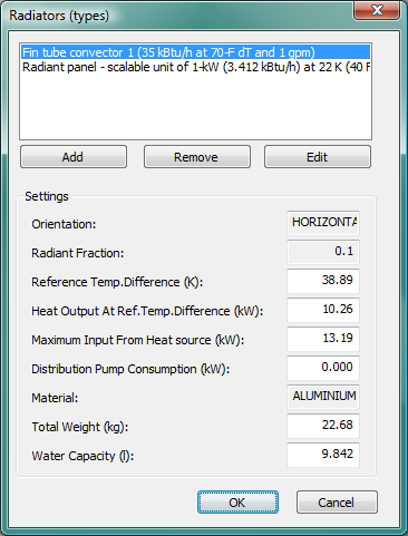
The Radiators (types) dialog supports defining radiator types for placement in the building. Each time a particular type is placed within a room component, this constitutes an additional instance of that type. Any given room can have more than one type and can have more than one instance of a particular type. However, keep in mind that a separate controller is required for each instance. Therefore, it is often worth limiting the number of instances to just one or two per zone by representing a range of grouped sets of radiators with types that represent their collective capacity and related characteristics.
Hot water radiators use the same calculation algorithms as the chilled ceiling module. The variation of convective heat transfer with radiator temperature is modeled using Alamdari and Hammond equations.
ApacheHVAC allows modeling of both TRV and modulated temperature controlled radiators. The program uses a simple parametric model that includes thermal mass and convective heat transfer coefficient that varies with radiator-to-room temperature delta-T.
Figure 5 - 3 : Radiator types dialog with pre-defined illustrative set of convective fin-tube baseboard heaters currently selected.
 Figure 5 - 4 : Radiator editing dialog showing inputs for a group of small wall-mounted steel radiators.
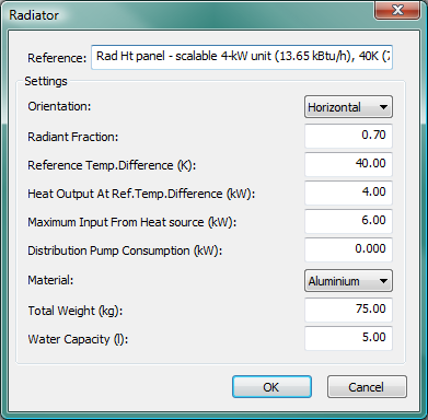
 Figure 5 - 5 : Editing dialog with for pre-defined scalable 4-kW unit overhead radiant heating panel (the 4-kW capacity is matched at conditions in the Reference with the pre-defined scalable 1-kW cooling panel).
Reference
Enter a description of the component. The reference is limited to 100 characters. It is for your use when selecting, organizing, and referencing any component or controllers within other component and controller dialogs and in the component browser tree. These references can be valuable in organizing and navigating the system and when the system model is later re-used on another project or passed on to another modeler. Reference names should thus be informative with respect to differentiating similar equipment, components, and controllers.
Orientation
Select an orientation to describe the orientation of the radiator. Standard radiators are vertically orientated, which will tend to increase the convective heat transfer coefficient within the overall heat transfer calculation. Use horizontal orientation when modeling an overhead radiant panel or a hydronic radiant heating floor system.
Vertical radiators or panels are mainly convective and horizontal radiators or panels are mainly radiative in their effect. The selected option therefore affects the default radiative fraction in the next cell. It is also used as a parameter to the Alamdari and Hammond convective heat transfer coefficient equations in determining the variation of the convective heat transfer coefficient with radiator/panel temperature.
Radiant Fraction
Enter the radiant fraction of the heat emitted from the device. For typical values see Table 13: Heat Emitter Radiant Fraction in the Apache Tables User Guide.
Reference Temperature Difference
Manufacturers’ data commonly gives heat output of the radiator at a specified unit-to-room reference temperature difference. Enter the reference temperature difference in this cell. For example, the data for a radiator may state that the heating output is 2.5 kW for a temperature difference of 60 ° C.
Heating Output at Reference Temperature Difference
Enter the reference heating output in this cell. For the example given above, the heating output is 2.5 kW for at the reference temperature difference of 60 ° C.
The program uses this data to calculate an effective area for use in the calculation of the convective heat transfer as follows:
A standard convective heat transfer coefficient HCIs is first calculated for the standard radiator-room temperature difference, ΔTu using the Alamdari and Hammond equations:
HCIs = F_HCIs (ORI,T su ,T sr ,CHARL)
where
T sr is the standard room temperature (set to 20ºC)
T su is the standard unit temperature (= T sr + ΔTu)
ORI is the Orientation
CHARL is the characteristic length (set to 0.1m)
F_HCIs is a function implementing the equations.
The effective area, Aeff is calculated as:
Aeff = Q std x (1 - rf)
_______________
HCIs x (Tbs - Trs)
where
Q std is the standard heat output at ΔTu and rf is the radiant fraction.
Note that the Alamdari and Hammond equations are used to set up the form of the variation of the convective heat transfer coefficient as the radiator and room temperatures vary and not to calculate absolute values from first principles. When the radiator-room difference is at ΔTu, the convective heat output from the unit is Q std x (1 - rf).
Maximum Input from Heat Source
Enter the maximum input from heat source serving the radiator. Because of the way in which heat source loads are calculated in the program, maximum heat source capacity cannot be specified. Instead, a maximum must be allocated to each heat emitter, coil, etc. The sum of the maximum capacities for all the devices on a heat source circuit should equal the maximum capacity of the heat source.
Distribution Pump Consumption
This item is included to allow for the electrical pumps on a secondary distribution circuit. Whenever the flow rate on/off controller is on, irrespective of the actual flow rate, then the full electrical power specified here will apply. This allows the modeling of zoned control of hot water distribution to radiators.
Material
Select the material from which the chilled ceiling panels or passive chilled beams are made (steel or aluminum). The material is used together with the 'Total weight' and the water capacity to calculate of the total thermal capacity of the radiator.
Radiator Weight
Enter the weight of the radiator or panel, excluding the weight of any water in the system. This data is used to calculate the thermal capacity of the radiator or panel device.
Note: If using a heating panel system to approximate a heated slab, it is essential that this weight reflect the mass of the concrete slab in which the tubes are embedded; however, this method of modeling a chilled slab should not be used in the case of a chilled floor that is exposed to direct-beam solar gain, as the chilled panel object cannot directly “see” the sun. For more information, see Error! Reference source not found. .
Water Capacity
Enter the water capacity of the radiator or panel. This data is also used in the calculation of thermal capacity for the radiator.
Chilled Ceilings
The Chilled Ceilings module allows you to create a set of chilled ceiling types for placement in the building and then control each instance of a particular type using flow rates, set points, and other control parameters specific to each particular zone.

Toolbar button for Chilled Ceiling Types list
Chilled Ceiling Types may be used to model primarily radiant chilled ceiling panels, primarily convective passive chilled beams, or anything in between. A hydronic cooling loop in a chilled concrete slab can also be modeled using a Chilled Ceiling Type to represent just the embedded water loop; however, care should be taken to modify the input values accordingly.
Active chilled beams, which flow a mixture of primary supply air and induced room air over a cooling coil, tend to have primarily convective heat transfer and relatively small radiant cooling effects. Active chilled beams should therefore be modeled on the airside network using a cooling coil and induced air loop with flow rate controlled in proportion to primary airflow. This is provided for the in the pre-defined “11b Active Chilled Beams [EWC chlr - HW blr]” system in the ApacheHVAC Systems Library.
The chilled ceiling module allows modeling of both cold-water flow and modulated temperature controlled devices. The program uses a simple parametric model that includes thermal mass and variable heat transfer with chilled ceiling temperature.
Chilled panel model in general
Output from the chilled ceiling component is calculated from the temperature difference between the metal surface and the room temperature. The software uses the Alamdari and Hammond equations to set up the form of the variation of the heat transfer coefficient as the chilled panel and room temperatures vary. Thus the output varies with the temperature difference between the panel and the room. In this calculation the room temperature is an average of air and radiant temperatures, weighted by convective and radiant heat transfer coefficients that vary with time according to conditions in the room.
For characterization of the radiant panel device and for the purpose of the design calculation, the room air and radiant temperatures are assumed to be the same, and equal to the metal temperature plus the reference temperature difference. During the subsequent simulation, the room air and radiant temperatures will tend not to be equal: Whereas it would be typical in summer for all room surfaces in room with an all-air cooling system to be somewhat warmer than the room air, when radiant cooling is engaged, most interior surfaces that can “see” the radiant panel will be cooler than the room air temperature; however, certain surfaces, such as window glass heated by direct solar radiation, may still be considerably warmer than the air temperature. The situation will therefore differ to some extent from the assumed design condition. Exactly how it differs is a function of room gains, room dynamics, and the dynamics of the waterside system and controls. These factors can't be fully anticipated in advance, so there will be some departure from the assumed design behavior. However, this can be corrected for by adjusting the design temperature difference in the light of simulation results at times of high load—e.g., for a space with a high fraction a radiant loads and cooling panels that also have a high radiant fraction for their cooling effect, setting the device radiant fraction appropriately in the Chilled Ceiling Types dialog and reducing the reference temperature difference will increase the cooling effect.
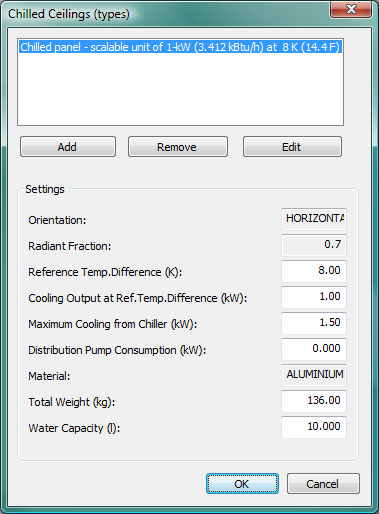
Figure 5 - 6 : Chilled ceiling (types) list
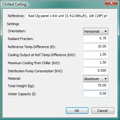
Figure 5 - 7 : Editing dialog with for pre-defined scalable (1-kW unit) overhead radiant cooling panel (the 1-kW capacity is matched at conditions in the Reference with the pre-defined scalable 4-kW heating panel).
Reference
Enter a description of the component. The reference is limited to 100 characters. It is for your use when selecting, organizing, and referencing any component or controllers within other component and controller dialogs and in the component browser tree. Reference names should be informative with respect to differentiating similar equipment, components, and controllers.
Panel Orientation
Select an orientation for the panels: horizontal for mainly horizontal panels—i.e. the majority of the chilled surface faces down toward the floor; vertical for wall-mounted panels or those with surface area mainly perpendicular to the floor and ceiling.
Vertical beams or panels are mainly convective and horizontal beams or panels are mainly radiative in their cooling effect. The selected option therefore affects the default radiative fraction in the next cell. It is also used as a parameter to the Alamdari and Hammond convective heat transfer coefficient equations in determining the variation of the convective heat transfer coefficient with beam temperature.
Horizontal panel orientation Vertical panel orientation
Radiant Fraction
Enter the radiant fraction of the heat emitted from the device. See Table 13 of the Apache Tables guide for some typical values.
|
Warning Limits
|
0.0 to 0.9
|
|
Error Limits
|
0.0 to 1.0
|
Reference Temperature Difference
Manufacturer’s data commonly gives the cooling output of the unit at a reference temperature difference. Enter the reference temperature in this cell. For example, the data may state that the cooling output is 2.5 kW for a unit-to-room temperature difference of 6 ° K—i.e., when the cooling surface of the unit is 6 ° K below the room air temperature.
|
Default (K)
|
5
|
|
Warning Limits (K)
|
2.0 to 20.0
|
|
Error Limits (K)
|
1.0 to 100.0
|
Cooling Output at Reference Temperature Difference
Manufacturers data commonly states cooling output for a given unit-room temperature difference. Enter this reference cooling output in this cell. For example the data may state that the cooling output is 2.5 kW for a temperature difference of 6K. In this case enter 2.5 in this cell.
The program uses this data to calculate an effective area for use in the calculation of the convective heat transfer as follows:
A standard convective heat transfer coefficient HCIs is first calculated for the standard panel-to-room temperature difference, ΔTb using the Hammond and Alamdari equations:
HCIs = F_HCIs(ORI,Tsb,Tsr,CHARL)
where
Tsr is the standard room temperature (set to 22 ° C)
Tsb is the standard beam temperature (= Tsr - ΔTb)
ORI is the Orientation
CHARL is the characteristic length (set to 0.1m)
F_HCIs is a function implementing the equations
The effective area, Aeff is calculated as:
Aeff = Qstd x (1 - rf)
_______________
HCIs x (Tbs - Trs)
where
Qstd is the standard heat output at Tbs and rf is the radiant fraction.
Note that the Alamdari and Hammond equations are used to set up the form of the variation of the convective heat transfer coefficient as the beam and room temperatures vary and not to calculate absolute values from first principles. When the beam is at Tbs and the room is at Trs, the convective heat output from the unit is Qstd x (1 - rf).
|
Warning Limits (kW)
|
0.35 to 100.0
|
|
Error Limits (kW)
|
0.05 to 9999.0
|
Maximum Cooling from Chiller
Enter the maximum input from chiller. In an actual application, this will be limited by the water temperature and flow rate. The parameters can also be controlled, and thus limited (see Room Unit Controllers section), however, this parameters allows opportunity for setting a hard limit in terms of available cooling capacity.
Because of the way in which chiller loads are calculated in the program, a maximum chiller capacity cannot be specified. Instead, a maximum limit must be allocated to each chilled ceiling, cooling coil, etc. Except where considerable diversity of cooling loads is anticipated, the sum of all the maximum capacities of all the devices on a cooling circuit should equal the maximum capacity of the chiller.
Distribution Pump Consumption
This item is included to allow for the electrical pumps on a zone-level secondary (or tertiary) hydronic loop. Whenever the flow rate on/off controller is on, irrespective of the actual flow rate, then the full electrical power specified here is assumed to apply. This allows the modeling of zoned control of cold-water distribution to chilled ceilings using local constant-speed pumps. Alternatively, such when only valves and not pumps are use at the zone loop level, pump power can be included on the secondary chilled-water loop at the system modeling level.
Panel Material
Select the material from which the chilled ceiling panels or passive chilled beams are made (steel or aluminum). The material is used together with the 'Total weight' and the water capacity' to calculate of the total thermal capacity of the beam.
Panel Weight
Enter the weight of just the panels or passive chilled beams, excluding the weight of water. This data is used to calculate thermal capacity.
Note: If using a chilled panel system to approximate a chilled slab, then it is essential that this weight reflect the mass of the concrete slab in which the tubes are embedded; however, this method of modeling a chilled slab should not be used in the case of a chilled floor that is exposed to direct-beam solar gain, as the chilled panel object cannot directly “see” the sun.
Panel Water Capacity
Enter the water capacity of the panels or passive beams. This is used to calculate the thermal capacity.