The fan module is used to determine the required fan power at a given flow rate, and thus energy consumption of the fan, and to account for the temperature rise in the air stream.


Toolbar buttons for placement of left and right intake fans


Left and right intake fan components
The fan component does not actively influence the flow rate; the values entered here do not determine airflow through the system. Rather, these values are used solely to calculate the consequential energy consumption and effect on air temperature at a given flow rate.
Pressure, in this case, refers to the total static pressure (internal plus external) to be overcome by the fan. Efficiency includes both the mechanical efficiency of the fan and the electrical efficiency of the motor and associated power electronics (e.g., a variable-speed drive). For variable-volume systems, the flow, pressure, and efficiency characteristics need to be defined at multiple points on the fan curve.
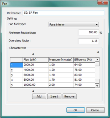
Figure 4 - 20 : Fan dialog with illustrative inputs (see section 8.3.7 Supply Fan for explanation of default values used in fans for pre-defined systems in the HVAC library).
The combination of flow, pressure, and efficiency is used during the simulation to calculate the electrical power consumption and fan heat input to the air stream as follows:
Where
Flow is airflow in kg/s
Pressure is the pressure resistance against which the fan has to work in Pa at Flow—typically between 50 and 200 Pa for local fans and between 500 and 2000 Pa for ducted fans.
r is the air density

Efficiency is the total (mechanical + electrical) fan efficiency
Energy loss = Electrical power × (1 – Efficiency)
Fan heat pickup = Electrical power × (1 – Efficiency) × Airstream heat pickup %
Where
Power is electricity consumption as calculated in the first fan equation, above.
Efficiency is total combined efficiency at a given flow rate for both the fan and motor.
Airstream heat pickup is the fraction of total fan and motor losses that go into the air stream.
It is important to realize that the fan curve data must account for the system layout (total pressure) and the type of airflow and fan controls. For example, the same fan would performance depending on whether it is controlled by a downstream damper or by variable-speed drive. In the system with speed control, the pressure either will drop with flow or will be maintained at a constant value as the basis for fan speed control (in either case, power and heat will fall with flow); whereas the damper-controlled system will have roughly constant speed, and therefore the pressure must rise as flow is reduced.
Reference
Enter a description of the component. The reference is limited to 100 characters. It is for your use when selecting, organizing, and referencing any component or controllers within other component and controller dialogs and in the component browser tree. These references can be valuable in organizing and navigating the system and when the system model is later re-used on another project or passed on to another modeler. Reference names should thus be informative with respect to differentiating similar equipment, components, and controllers.
Airstream Heat Pickup
Depending on whether the fan motor is in the airstream or not, there will be a greater or smaller heat pickup by the air across the fan. For fans whose motor is located in the airstream, a figure of 100% should be used. For fans where the motor is not located in the airstream, this will be less than 100%.
|
Warning Limits (%)
|
10.0 to 100.0
|
|
Error Limits (%)
|
0.0 to 100.0
|
Given that the values in the Efficiency column for the fan dialog are for the fan and motor combined, and the fact that no fan is perfectly efficient, an Airstream heat pickup value of 0, which is permitted as an input, would be rather unrealistic. This is the reasons for the warning limit at 10%.
Flow
Enter the fan flow rate. Up to five points may be defined on the fan characteristic curve.
|
Warning Limits (l/s)
|
0.0 to 25000.0
|
|
Error Limits (l/s)
|
0.0 to 900000.0
|
Pressure
Enter the total fan static pressure at this flow rate, including both internal pressure (resulting from filters, coils, and other air handler components) and external pressure (from ductwork, terminal units, etc.).
|
Warning Limits (Pa)
|
150.0 to 2000.0
|
|
Error Limits (Pa)
|
10.0 to 90000.0
|
Efficiency
Enter the fan total efficiency at this flow rate. This figure is used to calculate the electrical consumption of the fan at any instant, by dividing the work done on the air by the efficiency. The value entered here should be the product of the efficiencies of the impeller, drive, and motor.
|
Warning Limits (%)
|
25.0 to 90.0
|
|
Error Limits (%)
|
10.0 to 99.0
|