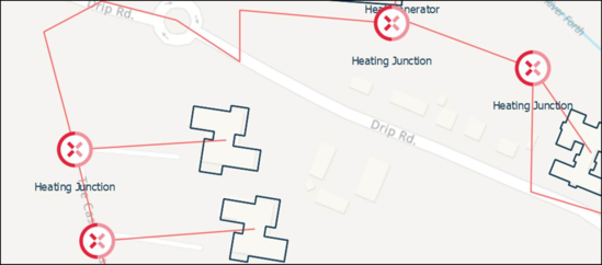
All assets required in the network must first be established within the virtual network of the project. Once the assets are added to the physical network the physical infrastructure of the heat network can now be drawn. This is done by right clicking on a building or asset and selecting “Draw Heating Network” from the pop-up. Every time a bend is required then left-click, and continue to do this until finally selecting the destination asset, as shown in the screengrab below.
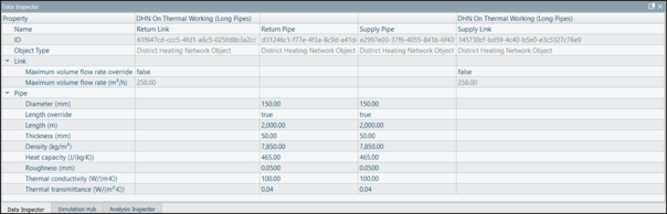
Each length specified consists of a Supply and Return pipe. The specific parameters of these pipes can be defined using the data inspector, a defined length can be implemented using the length override input.
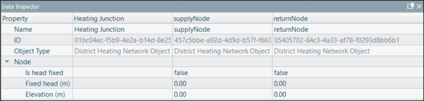
Heating junctions as shown above are used as junction points along the network. Heating junctions are draggable assets available from the asset library. Heating junctions are also used along a district heating network to specify the specific points elevation or the fixed head of a heat network along with the other heating network assets and buildings.
Note: Each heat network must only have one defined point with a fixed head value, with the fixed head set to 30m.
Heating junction data inspector input variables:
The data inspector outlines the specific inputs variables required when creating a district heating network for each asset involved. The data inspector below shows the input variables available for a specific run of pipes within a district heating network.
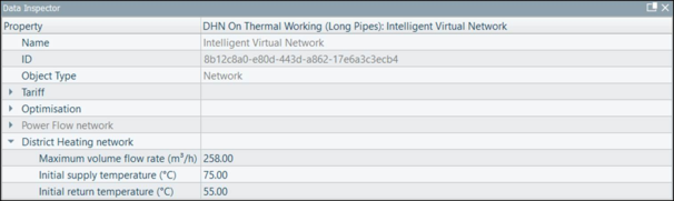
The district heating parameters for the network are set when the network as a whole is selected from the project browser. Outlining the maximum volume flow rate (m3 /h) of the system as well as the initial supply and return temperatures (˚C) of the system.
To add pumping stations (see section 4.17) to the district heating network, they must first be added to the virtual network before then being added to the physical network in the same way as a generation asset (ensuring that it is first connected to an electricity node in the virtual network so that it’s electrical demand is captured). Connection of the pumping station is done again by right clicking and selecting “draw heating pipe connection”.
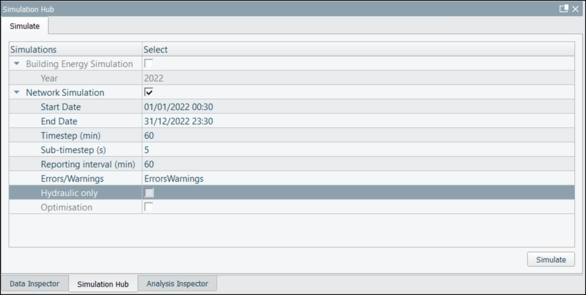
Once set up, the district heating simulation runs in parallel to the virtual network and is done via the Simulation Hub.
iVN Heat also has the option to run a ‘Hydraulic Only’ simulation allowing the user to only calculate a steady-state hydraulic problem to determine the head at each node, and the volume flow rate through each link of the network.
The hydraulic model is used for computing the flow rate and pressure head for each pipe. iVN uses the nodal method in combination with demand-driven analysis to assume a steady-state solution. This involves using the continuity equation- but as water is assumed to be incompressible and its properties are temperature invariant, the problem becomes framed in terms of volume flow rate.